
Introduction
Cold runner design determines how efficiently molten plastic travels from the injection machine to the mold cavity. A poorly designed runner system increases pressure loss, extends cycle time, creates filling imbalance, and wastes material. Simply enlarging runners does not improve molding performance because larger runners also require longer cooling and generate more runner scrap. The engineering objective is to deliver molten plastic to every cavity with minimum pressure loss while maintaining balanced flow, efficient packing, and economical material usage. Effective cold runner design therefore requires engineers to evaluate runner geometry, flow resistance, gate configuration, and part layout as one integrated system rather than independent design features.
Why Does Runner Geometry Control Filling Performance?
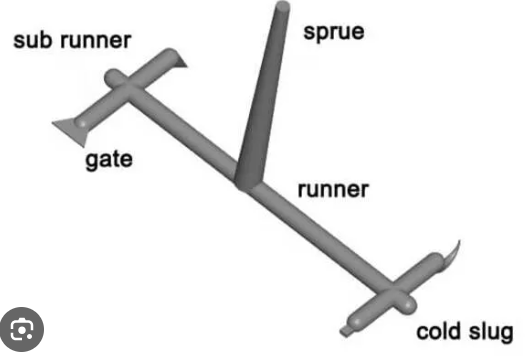
The runner is the first flow channel after the sprue. Every change in diameter, length, branch direction, and transition alters melt resistance before the material reaches the cavity.
The engineering relationship is straightforward:
runner geometry → pressure loss → cavity pressure → filling stability → part consistency
If the runner creates excessive resistance, the machine must generate higher injection pressure to fill the cavity. Higher pressure increases clamp force requirements and often narrows the molding process window.
For this reason, runner geometry should minimize unnecessary flow resistance instead of simply providing enough material volume.
During the injection mold design stage, engineers should evaluate runner length together with cavity layout. A shorter flow path usually produces lower pressure loss and more consistent cavity filling than a long, winding runner network.
Runner Diameter Should Balance Pressure Loss and Cooling Time
Increasing runner diameter reduces pressure loss because the molten plastic encounters less resistance.
However, larger runners also increase runner volume. More material must cool before mold opening, increasing cycle time and creating more scrap in cold runner production.
The objective is therefore not to design the largest possible runner. Instead, the diameter should provide sufficient melt flow while avoiding unnecessary cooling mass.
A properly sized runner minimizes injection pressure without significantly increasing cycle time.
Smooth Runner Transitions Reduce Flow Disturbance
Sharp corners and sudden diameter changes interrupt melt flow.
When molten plastic changes direction abruptly, local pressure loss increases and shear conditions become less uniform. These disturbances may contribute to hesitation, inconsistent cavity filling, or unstable pressure distribution.
Runner intersections should therefore use gradual transitions and generous radii whenever mold space allows.
Maintaining a smooth flow path produces more predictable filling than relying on higher machine pressure to overcome local restrictions.
How Does Runner Layout Affect Filling Balance?
Even with correctly sized runners, poor runner layout can prevent balanced filling.
In multi-cavity molds, each cavity should receive molten plastic under similar flow resistance. If one branch is significantly longer or contains additional restrictions, that cavity will fill differently from the others.
This relationship becomes especially important during DFM and mohttp://www.fentormold.com/injection moldld flow analysis, where filling sequence can be evaluated before steel cutting.
Symmetrical Runner Layout Improves Pressure Distribution
For identical multi-cavity molds, symmetrical runner layouts generally provide the best starting point.
Equivalent runner lengths and comparable branch geometry help each cavity receive similar melt pressure.
Geometric symmetry alone does not guarantee hydraulic balance, but it significantly reduces the likelihood of large pressure differences.
If complete symmetry is impossible because of part arrangement, runner dimensions can be adjusted to compensate for different flow resistance.
Family Molds Require Hydraulic Rather Than Geometric Balance
Family molds contain parts with different volumes and flow lengths.
Using identical runners for every cavity often produces filling imbalance because larger parts naturally require more melt and higher pressure.
Instead of copying the same runner dimensions throughout the mold, engineers should evaluate the pressure requirement of each cavity and adjust runner sizes accordingly.
The objective is balanced cavity filling—not identical runner geometry.
Why Must Gate Design Be Considered Together With the Runner?
The runner delivers molten plastic to the gate, but the gate determines how the melt enters the cavity.
A perfectly designed runner cannot compensate for an undersized or poorly positioned gate.
Likewise, increasing gate size cannot eliminate excessive pressure loss created by an inefficient runner.
The runner and gate therefore function as one flow-control system.
During prototype injection molding, engineers often evaluate gate freeze time, packing efficiency, and filling sequence together because changing either feature affects overall mold performance.
Gate Restriction Determines Local Pressure Loss
Every gate creates a controlled restriction between the runner and cavity.
A gate that is too small increases injection pressure and shortens packing time.
A gate that is too large may improve filling but increase gate vestige and extend cooling.
The correct gate size should satisfy filling, packing, appearance, and production requirements simultaneously.
Runner and Gate Should Freeze in the Correct Sequence
Cold runner systems depend on controlled solidification.
Ideally, the cavity should receive sufficient packing pressure before the gate freezes. Once packing is complete, the runner can solidify without affecting part quality.
If the gate freezes too early, the cavity cannot compensate for material shrinkage, increasing the risk of sink marks and dimensional variation.
Proper runner and gate sizing therefore improve both filling performance and part stability.
Engineering Conclusion
Successful cold runner design is achieved by controlling melt flow rather than maximizing runner size.
The engineering relationship is:
runner layout → pressure loss → gate performance → cavity filling → production stability.
A well-designed cold runner system minimizes unnecessary pressure loss, maintains balanced flow between cavities, and delivers adequate packing pressure without increasing cycle time or material waste.
Engineers should therefore optimize runner diameter, runner length, branch transitions, cavity layout, and gate design as one integrated flow system. When these variables work together, the mold operates within a wider processing window, produces more consistent parts, and requires fewer adjustments during production.