
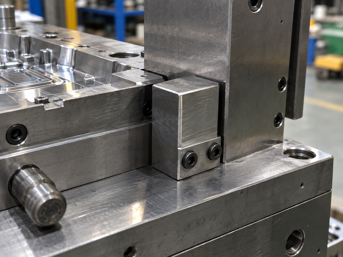
An injection mold limit switch may look like a small component, but its failure can cause serious mold damage.
On molds with sliders, hydraulic cylinders, core-pulling systems, ejector plates, or complex sequencing, the machine must know whether each mechanism has reached the correct position before the next movement starts.
If the signal is wrong, delayed, or missing, the machine may close the mold while a slider is still outside, move the ejector system before a core is fully retracted, or continue running when a mechanism is stuck.
The result can be much more expensive than replacing one switch.
It may cause broken cores, damaged sliders, bent ejector pins, damaged shut-off surfaces, or even major mold repair.
At Fentor Mold, we treat limit switches as part of the mold protection system rather than just an electrical accessory.
What Does an Injection Mold Limit Switch Do?
An injection mold limit switch confirms whether a moving mold component has reached a required position.
Typical applications include:
- Hydraulic core in / core out confirmation
- Slider position confirmation
- Ejector forward and return confirmation
- Mold plate movement confirmation
- Unscrewing mechanism position
- Two-stage ejection confirmation
- Special core-pulling sequences
For example, a hydraulic slider may have two position signals:
| Signal | Meaning |
|---|---|
| Core In | Slider has fully entered the molding position |
| Core Out | Slider has completely retracted |
| No Signal | Position is uncertain and the machine should stop |
The important point is simple:
The injection molding machine should never continue the next dangerous movement unless the required position has been confirmed.
Why Injection Mold Limit Switch Failure Can Damage the Mold
A limit switch itself normally does not carry mechanical load.
However, it controls the sequence of components that may carry very high loads.
Consider a hydraulic side core.
The normal sequence may be:
- Mold opens.
- Hydraulic core retracts.
- Limit switch confirms “core out.”
- Ejection starts.
- Part is removed.
- Core returns.
- Limit switch confirms “core in.”
- Mold closes.
If step 3 or step 7 gives an incorrect signal, the entire sequence becomes unsafe.
A mold closing against a partially extended core can create enormous impact force within a fraction of a second.
Therefore, a low-cost sensor can effectively protect components worth thousands of dollars.
Common Causes of Injection Mold Limit Switch Failure
An injection mold limit switch failure does not always mean that the switch itself is defective.
In many cases, the real problem comes from installation, wiring, mold movement, or environmental conditions.
1. Incorrect Switch Position
The switch must be activated at the correct mechanical position.
If it is installed too early, it may send a confirmation signal before the slider or core reaches its actual end position.
This is particularly dangerous.
For example:
The sensor says “core in,” but mechanically the core still has 2 mm of travel remaining.
The injection molding machine may then allow mold closing.
That remaining 2 mm can be enough to cause interference.
Therefore, the activation point should correspond to the actual safe mechanical position, not simply a convenient mounting location.
2. Loose Limit Switch or Bracket
Molds repeatedly experience:
- Vibration
- Opening and closing impact
- Hydraulic movement
- Temperature changes
- Long production cycles
As a result, a poorly secured switch bracket may gradually move.
Even a small positional change can affect the switching point.
This is why the sensor mounting structure should be rigid and easy to inspect.
3. Wiring Damage
Limit switch cables are another common weak point.
Typical problems include:
- Broken wires
- Loose connectors
- Damaged insulation
- Cable pinching
- Oil contamination
- Poor connector contact
The cable routing is especially important around moving mold sections.
A cable should never be positioned where a slider, ejector plate, mold plate, or machine clamp can crush it.
Whenever possible, wires should be fixed and protected.
4. Oil, Water, or Contamination
Injection molds operate in a difficult environment.
Limit switches may be exposed to:
- Lubricating oil
- Hydraulic oil
- Cooling water
- Dust
- Plastic residue
- Rust-prevention oil
Contamination may affect mechanical switches or electrical connections.
A cooling water leak near the sensor is particularly risky.
For this reason, sensor location should be considered during mold design rather than added casually after mold assembly.
5. Mechanical Components Do Not Reach the Expected Position
Sometimes the limit switch is working correctly.
The real problem is the mold mechanism.
For example, a slider may fail to reach its end position because of:
- Insufficient lubrication
- Wear
- Dirt between sliding surfaces
- Hydraulic pressure loss
- Damaged guide components
- Incorrect clearance
- Component deformation
This distinction is important.
If the machine repeatedly reports a position alarm, technicians should not immediately adjust the sensor closer just to eliminate the alarm.
The mechanism itself must be checked first.
Which Mold Components Need Limit Switch Protection?
Not every mold requires many sensors.
However, complex molds should use them where incorrect sequencing can create mechanical interference.
| Mold Mechanism | Main Risk Without Position Confirmation |
|---|---|
| Hydraulic slider | Mold closes before slider returns |
| Hydraulic core | Core collision or breakage |
| Ejector plate | Ejectors remain forward during closing |
| Unscrewing system | Thread core remains in wrong position |
| Two-stage ejection | Incorrect ejection sequence |
| Movable insert | Insert not seated before mold closing |
| Multiple cylinders | Cylinders move in wrong sequence |
The higher the potential collision risk, the more important reliable position feedback becomes.
How to Prevent Injection Mold Limit Switch Failure
Preventing failure requires both electrical and mechanical control.
Simply installing a good-quality switch is not enough.
Use Mechanical Stops Together With Sensors
A sensor should confirm position.
It should not define the mechanical end position by itself.
For example, a hydraulic slider should normally have a reliable mechanical stop.
The correct sequence is:
mechanical stop reached → sensor activated → signal sent to machine
This is much safer than allowing the switch body itself to act as the stop.
Otherwise, repeated impact may eventually move or damage the sensor.
Protect the Switch From Direct Impact
The switch should not be positioned where a moving mold component repeatedly hits it with excessive force.
A better design uses a controlled contact surface or sensing block.
This improves repeatability and extends service life.
The switch should also remain accessible enough for maintenance and replacement.
Check the Signal During Mold Trial
An injection mold trial should verify more than part quality.
The mold sequence should also be tested carefully.
For molds with limit switches, engineers should confirm:
- Core-in signal
- Core-out signal
- Ejector-return signal
- Correct machine interlock
- Correct movement sequence
- Stable signal after repeated cycles
Running only one or two manual cycles is not enough.
A sensor may appear stable initially but become unreliable after continuous movement.
At Fentor Mold, functional mold movement is checked during mold trials as part of overall tooling validation.
Do Not Bypass the Injection Mold Limit Switch
One of the most dangerous responses to a sensor problem is bypassing it simply to keep production running.
For example, an operator may see a repeated “core not returned” alarm.
Instead of checking the mold, someone modifies the machine signal or disables the protection.
Production starts again.
However, the original problem still exists.
If the hydraulic core later fails to retract completely, the machine may no longer stop before closing.
That can turn a small maintenance issue into major mold damage.
A protection signal should only be bypassed during controlled troubleshooting by qualified personnel—not as a production solution.
Add Mold Protection Through the Machine PLC
Modern injection molding machines can provide multiple layers of protection.
A good sequence may require several conditions before mold closing:
- Ejector completely returned
- Hydraulic core returned
- Slider position confirmed
- Robot safely outside
- Mold protection input normal
Only when all conditions are satisfied should the machine close at normal speed and pressure.
Low-pressure mold protection near the final closing position provides another layer of safety.
However, machine protection cannot replace correct mold design.
Both must work together.
Inspect Limit Switches During Injection Mold Maintenance
Limit switches should be included in the regular injection mold maintenance checklist.
Inspection does not take much time.
| Inspection Item | What to Look For |
|---|---|
| Sensor mounting | Loose screws or movement |
| Bracket | Cracks or deformation |
| Cable | Cuts, pinching, or worn insulation |
| Connector | Loose or contaminated contacts |
| Activation point | Correct mechanical position |
| Signal | Stable ON/OFF response |
| Moving mechanism | Smooth and complete travel |
| Mechanical stop | Wear or damage |
These checks become especially important after mold repair or component replacement.
Changing the position of a cylinder, slider, stop block, or bracket can also change the actual sensor activation point.
Limit Switch Alarm: Check the Mechanism Before Adjusting the Sensor
This is worth emphasizing.
Suppose the machine suddenly starts showing a core-position alarm after months of stable production.
Moving the sensor closer may make the alarm disappear.
But why did the core suddenly stop reaching its previous position?
Possible causes include:
- Wear
- Contamination
- Hydraulic pressure changes
- Loose components
- Damaged sliding surfaces
Adjusting the sensor without finding the reason may hide a developing mold problem.
What Should Buyers Check Before Mold Delivery?
For overseas molds, buyers should confirm the limit switch specification before shipment.
Important information includes:
- Switch brand and model
- Voltage requirement
- Connector type
- Wiring diagram
- Signal definition
- Spare sensor requirement
- Machine interface
- Core-in / core-out logic
This is especially important when the mold will run on a machine different from the one used by the mold supplier.
Machine interfaces vary between factories.
Therefore, electrical requirements should be confirmed early.
Before an overseas mold leaves our factory, Fentor Mold also checks mold functions, moving systems, and delivery preparation.
Final Thoughts
An injection mold limit switch is inexpensive compared with the mold components it protects.
However, the protection only works when the sensor, mechanical stop, wiring, machine logic, and mold movement are all correctly designed.
The most important rules are straightforward:
- Never use the switch itself as the mechanical stop.
- Confirm the actual end position before generating the signal.
- Protect cables and connectors.
- Do not bypass alarms during normal production.
- Investigate repeated alarms instead of simply moving the sensor.
- Check sensors during regular mold maintenance.
- Verify all safety sequences during mold trials.
For complex molds with hydraulic cores, sliders, or multi-stage movements, these details can prevent expensive collisions and unexpected downtime.
At Fentor Mold, we consider mold safety and movement sequencing during custom injection mold manufacturing because preventing one major collision can save far more than the cost of an entire protection system.