
Introduction
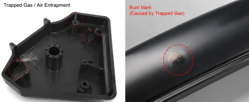
Injection mold venting is a critical factor that directly affects filling quality, surface appearance, and production stability. During injection molding, the molten plastic pushes the air inside the cavity toward the end of the filling path. If the trapped gas cannot escape fast enough, the compressed air creates high local pressure and temperature, causing burn marks, short shots, weak weld lines, and dimensional variation. These problems are often discovered during the first mold trial (T1), when engineers must identify whether the root cause comes from mold design, process settings, or material behavior. Proper venting design is therefore not only a cosmetic requirement but also a key factor in achieving stable mass production.
Why Poor Mold Venting Creates Injection Defects During FillingMeta Description
Poor venting happens when the cavity air cannot leave the mold before the plastic reaches the final filling area. The trapped air becomes compressed between the incoming melt front and the cavity wall. According to gas compression behavior, pressure and temperature increase rapidly when the available volume decreases.
The impact is not limited to visible defects. A poorly vented mold can change the actual filling pattern because the compressed gas creates resistance against the flowing plastic. The injection machine may show higher filling pressure, longer filling time, or unstable pressure transfer.
For complex plastic parts, especially automotive components and precision housings, venting problems can become more serious because the melt flow travels through multiple ribs, bosses, and thin wall sections. Engineers must evaluate the relationship between cavity geometry, filling direction, and gas escape path before mold manufacturing begins.
This is why professional mold design normally combines part analysis, gate location evaluation, and manufacturing feasibility review. During the mold development stage, engineers often perform injection mold design analysis to identify potential air trap areas before machining the mold steel.
How Trapped Gas Increases Cavity Pressure and Causes Burn Marks
When the melt reaches an area with poor exhaust, the remaining air has no effective escape channel. The injection pressure continues pushing the plastic forward, compressing the trapped gas in a small cavity space.
The compressed air temperature can rise significantly because the gas energy is converted into heat. This high-temperature gas damages the polymer surface and creates dark burn marks near the end of fill position.
The problem becomes more obvious with high-speed injection molding. Fast filling reduces the available time for gas movement, increasing the possibility of diesel effect burning. Increasing injection speed may improve filling, but it can also make venting defects worse if the mold exhaust system is insufficient.
Why Poor Venting Creates Filling and Surface Quality Problems
Poor venting can create incomplete filling because trapped air acts like a barrier against the incoming melt. Thin ribs, deep pockets, and narrow channels are common locations where air remains trapped.
In production, engineers may mistakenly increase melt temperature or injection pressure to solve short shots. However, these adjustments only increase the stress on the mold system. Higher temperature can improve flow but may also increase material degradation and surface defects.
A better solution is to check whether the mold provides a suitable exhaust path. For precision components requiring stable dimensions, controlling mold structure and manufacturing accuracy is equally important. A complete plastic injection molding process evaluation helps connect mold design, material behavior, and production parameters together.
How Mold Venting Design Affects Injection Molding Stability
Mold venting design is not simply adding grooves on the parting line. Engineers must determine where gas accumulates, how fast the melt reaches these areas, and how much exhaust capacity is required.
The ideal venting system allows air and gas to escape while preventing molten plastic leakage. The design must balance vent depth, width, land length, and location according to material characteristics and part geometry.
Different materials also create different venting requirements. High viscosity materials usually need more effective exhaust because they move slower and trap gas more easily. Filled materials may create additional gas because additives, moisture, and thermal decomposition products can increase vent contamination.
How Injection Pressure and Melt Temperature Influence Gas Exhaust
Injection pressure directly affects how strongly the melt compresses trapped gas. Higher pressure can improve filling speed but increases the risk of gas compression when venting capacity is limited.
Melt temperature changes plastic viscosity. Higher melt temperature reduces resistance and allows easier flow, but excessive temperature can generate more volatile gas from material degradation.
The correct approach is not simply increasing or decreasing one parameter. Engineers need to understand the relationship between pressure, temperature, and material flow behavior.
For example, when molding engineering plastics, stable temperature control is especially important because overheating may create additional gas and surface defects. This is also why projects involving high temperature plastic injection molding require careful evaluation of mold temperature, vent design, and processing window.
How Vent Location and Vent Dimension Control Filling Performance
Vent position determines whether trapped air can escape before the melt completely seals the area.
The most effective vent locations are usually at the final filling position, weld line area, deep ribs, and locations where multiple melt flows meet. Incorrect vent placement may leave air trapped even when vents exist.
Vent dimension also affects performance. A vent that is too shallow cannot remove enough gas. A vent that is too deep may allow plastic leakage and create flash.
The correct vent size depends on material viscosity, part thickness, injection speed, and mold surface requirements.
Why Venting Problems Often Cause T1 Mold Trial Failure
Many T1 failures are not caused by incorrect mold dimensions or machining errors. Instead, poor gas management during filling is often the hidden reason behind unstable results.
During the first trial, engineers usually focus on short shots, flash, sink marks, and appearance problems. However, several defects may have the same root cause: incorrect exhaust design.
A mold may run correctly at low speed but fail during production conditions when cycle time requirements increase. This difference explains why some molds pass initial testing but show quality problems after mass production starts.
How Flow Behavior Creates Air Traps at the End of Fill
Melt flow behavior determines where air will finally collect.
When plastic enters the cavity, the flow front pushes air forward. The last filled area becomes the highest-risk location for gas accumulation.
Complex parts with uneven wall thickness often create unpredictable flow patterns. Thin sections may freeze early, preventing air from escaping through normal paths.
During mold development, simulation tools can predict filling balance, weld line position, and potential air trap locations before production. This reduces unnecessary mold modification after T1 testing.
How Vent Blocking Changes Production Consistency
Even a correctly designed venting system can lose performance over time.
During production, resin decomposition products, dust, and additives can gradually block vent channels. The result is a slow increase in cavity pressure and unstable part quality.
A typical production issue occurs when the first thousands of parts are acceptable, but later parts begin showing burn marks and short shots. Engineers may first adjust machine parameters, but the actual problem is reduced vent efficiency.
Regular mold maintenance and vent inspection are therefore necessary for long-term production stability.
How Engineers Optimize Mold Venting for Stable Production
A successful venting solution requires cooperation between mold design, simulation, and process control. Changing only injection parameters cannot permanently solve a mold design problem.
Engineers should identify the root cause before modifying the tool. If the problem comes from gas accumulation, increasing injection pressure or temperature may only hide the issue temporarily.
A stable production mold needs a complete system that includes proper exhaust paths, balanced filling, suitable material processing, and accurate mold manufacturing.
How Mold Flow Analysis Predicts Venting Risks
Mold flow analysis provides valuable information about melt movement before physical testing.
Engineers can evaluate filling sequence, pressure distribution, weld line location, and air trap positions. This allows vent locations to be optimized before machining.
For complicated molds, combining simulation with professional mold manufacturing services can reduce T1 modification cycles and improve project delivery reliability.
How Process Adjustment Works Together With Mold Modification
When venting defects appear, process adjustment should be used together with mold improvement.
Reducing injection speed may give trapped gas more time to escape. Adjusting melt temperature may improve flow balance. However, these methods have limits.
If the mold design does not provide sufficient exhaust capability, process changes cannot completely solve the problem.
The final engineering decision should focus on removing the cause rather than controlling the symptom. A production-ready injection mold must maintain stable gas evacuation under actual manufacturing conditions.
Engineering Conclusion
Injection mold venting is a fundamental design factor that directly influences T1 success and long-term production stability. Burn marks, incomplete filling, weld line weakness, and dimensional variation are often signs of uncontrolled gas behavior inside the cavity.
The most reliable solution is to treat venting as part of the complete mold filling system. Engineers must evaluate melt flow direction, pressure development, temperature influence, and vent design together.
A well-designed venting system reduces trial-and-error modification, improves production consistency, and allows injection molds to achieve stable performance from initial testing through mass production.