
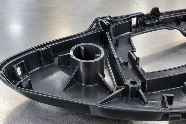
A good crush rib design can solve a common problem in injection molded assemblies: how do you create a tight fit without making the whole mating surface too tight?
Instead of using full-surface interference, crush ribs create several small contact points. During assembly, these ribs deform slightly. As a result, they can hold a shaft, pin, insert, or another plastic part firmly in position.
This approach can also help manage molding tolerances. In addition, it can reduce excessive assembly force.
At Fentor Mold, we often review mating features during DFM. The goal is not only to make the part moldable. The assembly must also work after production tolerances, shrinkage, and material behavior are considered.
What Is Crush Rib Design?
A crush rib is a small raised feature placed on a mating surface.
It is commonly used inside:
- Round holes
- Plastic bosses
- Cylindrical openings
- Sleeves
- Locating features
- Press-fit areas
When another component enters the feature, the ribs contact it first.
The ribs then compress or deform slightly.
Because only a small area creates the interference, the assembly force can stay lower than with a full interference fit.
At the same time, the ribs help remove unwanted clearance.
How Does Crush Rib Design Work?
Imagine a metal shaft that needs to fit into a molded plastic hole.
If the hole is too large, the shaft may wobble.
However, making the whole hole smaller creates another problem. Small molding changes may make the fit too tight.
A crush rib design offers another option.
The main hole can provide enough clearance for assembly. Then several small ribs create the required interference.
During insertion, those ribs deform locally.
Therefore, the designer can achieve a tighter fit without forcing the entire inner wall against the shaft.
This is one reason crush ribs are useful in parts with normal injection molding variation.
Why Use Crush Ribs Instead of a Full Press Fit?
A traditional press fit relies on the dimensions of two complete mating surfaces.
For example, a 10 mm shaft may enter a hole that is slightly smaller than 10 mm.
That sounds simple. However, plastic parts do not always hold one exact dimension.
Several factors can change molded dimensions:
- Resin shrinkage
- Mold temperature
- Holding pressure
- Material lot
- Moisture
- Tool wear
- Part geometry
- Environmental temperature
Therefore, a full interference fit may behave differently from one production batch to another.
Crush ribs give the design more room to absorb these small variations.
As a result, assembly can become more stable.
Crush Rib Design for Tolerance Compensation
Tolerance compensation is one of the most useful benefits of crush rib design.
Suppose a molded hole has a normal manufacturing tolerance.
The mating shaft also has its own tolerance.
If both dimensions move toward the tight side, assembly force may become too high.
On the other hand, if both move toward the loose side, the assembly may wobble.
Crush ribs can help reduce this problem.
The main hole provides clearance. Meanwhile, the ribs provide controlled local contact.
Therefore, small dimensional changes do not always affect the complete mating surface.
This can give the assembly a wider working window.
Crush Rib Design and Injection Molding Draft
Draft is important in injection molding because it helps the molded part release from the tool.
However, draft can create a problem in a precision mating hole.
A drafted hole changes diameter along its depth. Therefore, it may not provide the straight contact needed for a stable press fit.
One possible solution is to use a drafted main hole with local crush ribs.
The main surface can then support easier mold release. Meanwhile, the ribs provide the contact needed for alignment and retention.
This concept can be useful when moldability and assembly requirements conflict.
For a broader view of draft, ribs, wall thickness, gates, and other part-design factors, you can also read our Injection Mold Design Guide: Process, Tips & Best Practices.
Where Should Crush Ribs Be Located?
Rib position has a major effect on assembly performance.
The ribs should contact the mating component in the areas that need support.
For a round shaft, designers often distribute contact points around the inside diameter.
Balanced positioning helps keep the mating component centered.
However, more ribs are not automatically better.
Too many contact points can increase:
- Assembly force
- Material stress
- Tooling complexity
- Risk of cracking
Therefore, the number and location should match the real function of the assembly.
How Much Interference Should a Crush Rib Have?
There is no single interference value that works for every crush rib design.
The correct amount depends on:
- Plastic material
- Rib geometry
- Shaft material
- Part size
- Required retention
- Assembly method
- Working temperature
For example, PP can tolerate more local deformation than some rigid or glass-filled plastics.
Meanwhile, PA66 GF30 behaves very differently from soft PP.
A very large interference may increase retention. However, it can also create excessive stress.
This may cause:
- Rib damage
- Boss cracking
- High assembly force
- Stress whitening
- Part deformation
For this reason, the interference should be tested with the actual material and assembly.
Material Selection for Crush Rib Design
Material behavior matters just as much as geometry.
More ductile plastics usually tolerate local rib deformation better.
Examples may include:
- PP
- PE
- ABS
- Some nylon grades
- POM
However, the exact grade matters.
A reinforced resin can be much stiffer than an unfilled version of the same polymer.
For example, PA66 GF30 will not deform like unfilled PA66.
Therefore, simply copying the same rib geometry from one material to another can create problems.
Material stiffness, elongation, temperature, and long-term creep should all be considered.
Crush Rib Design for Metal Inserts and Shafts
Crush ribs are often useful when a plastic part mates with a metal component.
Typical examples include:
- Metal pins
- Shafts
- Bushings
- Tubes
- Bearings
- Sleeves
- Small inserts
Metal parts usually deform much less than plastic ribs.
As a result, most of the local movement occurs in the plastic.
This can create a stable fit while keeping assembly relatively simple.
However, the design should still avoid excessive stress around the boss or hole.
A thin plastic wall around the press-fit feature may crack even if the ribs themselves look correct.
Crush Rib Design for Plastic-to-Plastic Assembly
Crush ribs can also work between two molded plastic parts.
For example, one part may have a cylindrical post. The second part may have a mating hole with ribs.
During assembly, the ribs create controlled friction and remove clearance.
This approach can help reduce:
- Rattle
- Wobble
- Loose assembly
- Alignment variation
However, plastic-to-plastic assembly needs extra care.
Both parts can deform.
Therefore, designers should consider the stiffness of both materials rather than only the ribbed part.
How Rib Shape Affects Crush Rib Performance
The shape of the rib controls how it contacts the mating part.
A narrow contact area usually deforms more easily than a wide flat surface.
Therefore, a narrow or rounded rib tip can reduce the contact area during initial assembly.
However, tooling also matters.
Very sharp rib geometry may require more difficult mold machining.
A rounded profile can sometimes simplify manufacturing while still creating a small contact area.
For production tooling, this should be reviewed before mold machining begins.
The best geometry should balance:
- Assembly function
- Moldability
- Tooling cost
- Part strength
Crush Rib Design and Assembly Force
Assembly force is one of the most important design checks.
If the force is too low, the component may become loose.
If it is too high, production can become difficult.
High force can also damage the part.
Assembly force depends on several factors:
- Rib interference
- Rib length
- Number of ribs
- Material stiffness
- Surface friction
- Shaft size
- Lead-in geometry
For manual assembly, excessive force can slow production.
For automated assembly, force variation can create machine or quality problems.
Therefore, prototype testing is useful before final tooling is locked.
Why a Lead-In Helps Crush Rib Assembly
A sudden interference at the entrance can make assembly difficult.
Instead, a small lead-in or chamfer can help guide the mating component into position.
This reduces the initial impact on the rib.
It can also prevent:
- Rib shaving
- Edge damage
- Misalignment
- Sudden high insertion force
For this reason, the entrance geometry should be reviewed together with the ribs.
The design should guide the mating component before full interference begins.
Crush Rib Design Around Plastic Bosses
Bosses are common locations for crush ribs.
For example, a molded boss may receive a metal pin or another plastic post.
However, boss wall thickness is important.
If the wall is too thin, the press fit can split the boss.
If the wall is too thick, molding defects may appear.
These can include:
- Sink marks
- Voids
- Long cooling time
- Uneven shrinkage
Therefore, increasing the boss size is not always the best solution.
Good rib and boss design should provide enough strength without creating thick plastic sections that cool unevenly.
If you are working on ribs, bosses, or thick local features, our article on Common Injection Molding Defects and How to Fix Them also explains how part geometry can contribute to sink marks, warpage, and other molding problems.
You can also learn more about our custom injection mold manufacturing process, including DFM, mold design, machining, assembly, and mold trials.
Common Crush Rib Design Problems
A crush rib is a small feature, but poor design can create large assembly problems.
Too Much Interference
Excess interference can increase insertion force.
In addition, it may crack the boss or damage the rib.
Too Little Interference
If the rib barely contacts the mating part, it may not control movement.
As a result, the assembly can remain loose.
Ribs That Are Too Wide
Wide ribs create more contact area.
Therefore, they may behave more like a full interference fit.
Poor Rib Distribution
If all contact points sit on one side, the shaft can move away from center.
Balanced contact is usually more stable.
No Assembly Lead-In
Without a lead-in, the mating component can hit the rib edge directly.
This can shave or damage the rib.
When Should You Use Crush Rib Design?
A crush rib design is worth considering when you need:
- A tight plastic-to-metal fit
- A tight plastic-to-plastic fit
- Better alignment
- Reduced wobble
- Tolerance compensation
- Controlled local interference
- Easier assembly than a full press fit
- Draft on the main molded surface
It can be especially useful when the mating dimensions have enough variation to make a full interference fit risky.
When Should You Avoid Crush Ribs?
Crush ribs are not suitable for every assembly.
Avoid using them without further review when:
- The part must be removed repeatedly
- Very high pull-out force is required
- The plastic is extremely brittle
- Creep could reduce retention over time
- Assembly force is tightly controlled
- The feature carries high structural loads
- The mating dimensions are highly critical
In these cases, another joining method may work better.
Options can include:
- Snap fits
- Screws
- Heat staking
- Ultrasonic welding
- Metal inserts
- Adhesive
- Mechanical locking features
The assembly method should match the product’s life and loading conditions.
Crush Rib Design vs Snap Fit
Crush ribs and snap fits solve different problems.
A crush rib mainly creates friction and interference.
A snap fit usually creates a mechanical lock.
Therefore, a snap fit may provide better retention when pull-out force is important.
However, snap features require more space and more complex geometry.
Crush ribs are often simpler when the main goal is:
- Positioning
- Alignment
- Light retention
- Removing clearance
In some products, both methods can even be used together.
Crush Rib Design vs Standard Interference Fit
A standard interference fit uses most or all of the mating surface.
This can provide strong retention.
However, it also makes the assembly more sensitive to dimensional variation.
Crush ribs reduce the contact area.
As a result, they can offer more local deformation and a wider tolerance window.
That does not mean crush ribs are always better.
For high-load applications, a full interference fit may still be more suitable.
The correct choice depends on retention force, material, assembly method, and product life.
Does Crush Rib Design Increase Mold Cost?
Usually, the cost impact is small when the ribs are simple and easy to machine.
However, geometry matters.
Very small or sharp features may require additional machining work.
They can also make polishing and mold maintenance more difficult.
Therefore, crush ribs should be reviewed during DFM rather than added after the tool is finished.
At Fentor Mold, we prefer to identify these assembly features before steel cutting.
For projects that continue into mass production, our injection molding production service also allows the fit to be checked during mold trials and production sampling.
Should You Prototype Crush Rib Design Before Production?
For important press-fit assemblies, prototype testing is useful.
CAD dimensions alone cannot fully show how the real assembly will feel.
You can test:
- Insertion force
- Pull-out force
- Wobble
- Alignment
- Rib damage
- Stress whitening
- Repeated assembly
- Temperature effects
This is especially useful when the mating component is metal.
For early design validation, prototype injection molding can help verify actual molded shrinkage and fit before committing to long-term production tooling.
Crush Rib Design: Final Design Checklist
Before releasing a crush rib feature for tooling, check the following:
- Is a crush rib really needed?
- Does the main mating feature have enough clearance?
- Is the interference realistic for the selected material?
- Are the ribs distributed evenly?
- Is there a lead-in for assembly?
- Is the surrounding wall strong enough?
- Will draft affect the mating function?
- Can the rib geometry be machined easily?
- Has the assembly force been considered?
- Has the design been tested with real molded parts?
A small design change at this stage can prevent a much larger tooling change later.
Final Thoughts on Crush Rib Design
A good crush rib design provides controlled interference without forcing the entire mating surface into a tight press fit.
This makes it useful for tolerance compensation, alignment, and light retention in many injection molded assemblies.
However, the rib should not be designed by itself.
Material, wall thickness, draft, interference, assembly force, and mold machining all affect the final result.
For this reason, the best time to review crush ribs is during DFM, before mold manufacturing begins.
When the fit is critical, testing real molded samples is also important. This allows the rib height or mating dimension to be adjusted before the mold enters stable production.