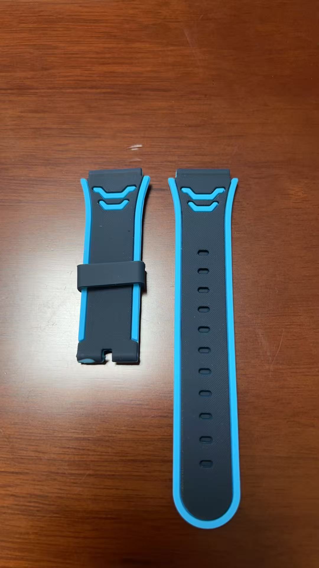
LSR overmolding combines liquid silicone rubber (LSR) with a rigid plastic, metal, or another substrate to create one integrated component. It is widely used when a product needs sealing, flexibility, insulation, soft-touch surfaces, or resistance to heat and environmental exposure.
However, LSR overmolding is not simply a matter of injecting silicone onto an existing plastic part. The substrate must tolerate the molding temperature. Bonding must also be considered early. In addition, the mold needs very accurate shut-offs because low-viscosity LSR can flow into extremely small gaps.
At Fentor Mold, we evaluate these factors during the DFM and tooling stages. This helps reduce bonding failures, flash, substrate deformation, and expensive mold modifications later in the project.
What Is LSR Overmolding?
LSR overmolding is a molding process in which liquid silicone rubber is injected around or onto an existing substrate.
The substrate may be:
- Thermoplastic
- Metal
- Previously molded plastic
- Insert component
- Other compatible engineered materials
After injection, heat cures the LSR and forms the final elastomer layer.
Therefore, a single finished component can combine the rigidity of the substrate with the flexibility of silicone.
Typical applications include:
- Medical device components
- Electrical seals
- Automotive connectors
- Waterproof components
- Valve membranes
- Sensor components
- Soft-touch grips
- Electronic protection parts
- Sealing interfaces
Unlike many thermoplastic elastomers, LSR is a thermoset material. Once cured, it cannot simply be melted and reshaped like conventional thermoplastics.
Why Use LSR Overmolding?
The main reason to use LSR overmolding is to combine properties that one material cannot easily provide.
A rigid thermoplastic can provide dimensional stability and structural strength. Meanwhile, silicone can provide flexibility, sealing, temperature resistance, and a soft contact surface.
As a result, manufacturers can sometimes eliminate separate seals or secondary assembly operations.
Better Sealing Performance
LSR can form flexible sealing surfaces directly around a rigid component.
This makes it useful for:
- Waterproof connectors
- Electronic seals
- Fluid-handling components
- Medical components
- Automotive electrical systems
However, the sealing geometry must have sufficient compression and dimensional control.
Improved Product Integration
Instead of manufacturing a plastic component and silicone seal separately, LSR overmolding can integrate both into one component.
Consequently, the finished product may require fewer assembly steps.
Complex Soft-and-Rigid Structures
Because LSR flows very easily, it can fill thin and detailed geometries. This gives product designers more freedom when designing flexible features around rigid structures.
LSR Overmolding Bonding: The Most Important Material Question
Bonding is one of the most important considerations in LSR overmolding.
Silicone does not automatically bond strongly to every plastic or metal.
Therefore, engineers should never assume that two materials are compatible simply because both can survive the molding process.
Several bonding approaches are available.
Self-Bonding LSR
Some LSR grades contain adhesion technology designed to bond directly to selected thermoplastics or metals.
For example, commercial self-bonding LSR grades are available for substrates such as selected nylons, PBT, copolyesters and metals. However, compatibility depends on the exact LSR grade and substrate grade.
Other self-bonding silicone systems have also been developed for materials such as selected PC and polyester substrates.
Therefore, designers should always check the silicone supplier’s compatibility data rather than relying only on the generic material name.
For example:
“LSR + PC” is not enough information.
The actual result can depend on:
- Exact PC grade
- Additives
- Flame retardants
- Glass reinforcement
- Color masterbatch
- Surface contamination
- LSR formulation
- Mold temperature
- Cure time
Testing the actual production materials before final tooling is therefore a safer approach.
Mechanical Interlocks in LSR Overmolding
Chemical bonding should not always carry the entire mechanical load.
When long-term retention is critical, designers can add a mechanical interlock.
Common designs include:
- Through holes
- Undercut grooves
- Slots
- Retention channels
- Anchor features
- Wrap-around structures
The LSR flows through or around these features and becomes mechanically locked after curing.
Mechanical retention can supplement chemical adhesion or provide retention where chemical bonding is unreliable. This approach is also commonly recommended for critical overmolding applications.
For parts exposed to pulling, twisting, vibration, or repeated cycling, combining chemical bonding with mechanical retention can often create a more robust design.
Which Substrate Materials Work With LSR Overmolding?
The substrate must meet two basic requirements:
- It must survive the LSR molding temperature.
- It must provide suitable bonding or mechanical retention.
LSR processing can involve relatively high mold temperatures. Therefore, low-temperature plastics may soften, warp, or lose dimensional stability during overmolding.
Typical engineering materials considered for LSR applications may include:
| Substrate | LSR Overmolding Consideration |
|---|---|
| PBT | Common engineering substrate; bonding depends on grade |
| PA / Nylon | Suitable for selected LSR systems |
| PC | Possible with compatible self-bonding LSR grades |
| PEI | Good temperature resistance |
| PEEK | Excellent temperature resistance but higher material cost |
| Metal | Often suitable with correct surface/bonding system |
| ABS | Temperature and bonding require careful evaluation |
| PP | Bonding can be challenging without a suitable system |
For example, Protolabs notes that high LSR molding temperatures can create problems for some lower-temperature thermoplastics, while materials such as PBT and glass-filled nylon can be better suited to certain applications.
Therefore, substrate selection should happen before the mold structure is finalized.
LSR Overmolding Part Design Considerations
Good product design can significantly reduce tooling and production problems.
Provide Enough Bonding Area
A very narrow silicone-to-plastic interface gives the bond less surface area.
Whenever possible, provide enough contact area between the LSR and substrate.
However, adding bonding area alone does not guarantee success. Material compatibility and processing conditions remain important.
Avoid Sharp Silicone Corners
Sharp internal corners can create stress concentration.
Because silicone is flexible, designers sometimes assume sharp geometry will not matter. In reality, sharp transitions can still increase the risk of tearing during demolding or service.
Adding suitable radii can improve durability. LSR design guidance also recommends avoiding unnecessary sharp edges where tearing could occur.
Control Silicone Thickness
Very thin LSR sections may be possible because the material flows well. However, extremely thin regions can still create filling and tearing problems.
At the same time, unnecessarily thick silicone areas may:
- Increase material consumption
- Extend curing time
- Increase cycle time
- Affect dimensional behavior
The thickness should therefore match the functional requirement.
LSR Overmolding Tooling Requires Excellent Shut-Off Control
One of the biggest tooling differences between thermoplastic molding and LSR molding is flash control.
LSR has very low viscosity before curing.
As a result, silicone can enter tiny mold gaps that would not normally cause problems with conventional thermoplastic injection molding.
That means the mold requires:
- Accurate mold inserts
- Precise parting surfaces
- Stable mold alignment
- Controlled shut-off areas
- Proper steel fitting
- Good insert support
Even a small mismatch between the substrate and cavity can allow LSR to escape into an unwanted area.
For this reason, precision injection mold manufacturing becomes especially important for LSR overmolding projects.
How Should the Substrate Be Located in the Mold?
The first-shot plastic part or insert must remain stable while the LSR enters the cavity.
If the substrate moves, several defects can appear:
- Uneven silicone thickness
- Flash
- Incorrect sealing geometry
- Exposed substrate
- Dimensional variation
- Bonding inconsistency
Therefore, the mold should locate the substrate positively.
Depending on the part, engineers may use:
- Pins
- Mold cores
- Datum surfaces
- Mechanical nests
- Vacuum positioning
- Automated loading fixtures
The locating system should control movement without damaging the first-shot component.
Gate Design for LSR Overmolding
Gate location affects both filling and bonding.
The flow should reach the bonding surface without creating excessive trapped air or unnecessary pressure.
Engineers should consider:
- Flow direction
- Bonding interface
- Thin sections
- Air traps
- Cosmetic requirements
- Silicone thickness
- Weld or knit areas
- Gate removal
In complex components, simulation or filling analysis can help identify potential risks before mold manufacturing begins.
This is especially valuable when the LSR must travel through narrow sealing channels or around several rigid features.
Venting Is Critical in LSR Tooling
Air must escape as the silicone fills the cavity.
Poor venting can cause:
- Incomplete filling
- Burn marks
- Air pockets
- Weak bonding areas
- Surface defects
However, vent design requires extra care because LSR can also flow into extremely small vents.
Therefore, vent dimensions, locations, and shut-off conditions must be carefully controlled.
Preventing Flash in LSR Overmolding
Flash is one of the most common concerns in LSR overmolding.
Possible causes include:
- Poor mold fitting
- Incorrect substrate dimensions
- Insufficient clamping
- Damaged shut-off surfaces
- Incorrect injection pressure
- Incorrect cavity venting
- Substrate warpage
The first-shot plastic component also becomes part of the second mold’s sealing system.
Therefore, variation in the plastic substrate can directly affect LSR flash.
This is an important difference compared with standard single-material injection molding.
If the plastic part varies too much in thickness or flatness, the LSR mold may not seal consistently.
Insert Molding or Two-Shot LSR Overmolding?
LSR overmolding can be produced using different manufacturing strategies.
Insert Overmolding
First, manufacture the plastic substrate.
Then place it into another mold and inject LSR around it.
This approach can be suitable for:
- Lower production volumes
- Larger components
- Existing plastic inserts
- Projects requiring flexible tooling investment
Manual or robotic loading can be used depending on volume.
Two-Shot or Multi-Material Molding
For higher production volumes, the plastic and silicone stages may be integrated into a more automated production process.
This can provide:
- Shorter handling time
- Better positioning consistency
- Reduced manual labor
- Higher production efficiency
However, the tooling and molding equipment are usually more complex.
If you are comparing multi-material processes, our guide to Two-Shot Molding vs. Overmolding explains the main differences.
LSR Overmolding vs TPE Overmolding
LSR and TPE can both create flexible surfaces around rigid plastic components, but they behave very differently.
| Factor | LSR | TPE |
|---|---|---|
| Material type | Thermoset silicone | Thermoplastic elastomer |
| Processing | Heat-cured | Melted and cooled |
| Temperature resistance | Generally high | Grade dependent |
| Flexibility | Excellent | Excellent |
| Re-melting | No | Yes |
| Bonding | Grade/substrate dependent | Grade/substrate dependent |
| Flash sensitivity | Very high | Generally lower |
| Medical applications | Widely available | Grade dependent |
Therefore, neither material is automatically better.
The final choice depends on:
- Operating temperature
- Chemical environment
- Sealing requirements
- Hardness
- Regulatory requirements
- Production volume
- Substrate material
- Tooling budget
You can also read our TPE Overmolding Guide for a comparison with thermoplastic elastomer overmolding.
Common LSR Overmolding Problems
Even a good-looking CAD model can create molding problems if the interface between the two materials has not been properly evaluated.
Weak Bonding
Possible causes include:
- Incompatible material combination
- Contaminated substrate
- Incorrect surface treatment
- Insufficient curing
- Incorrect substrate temperature
- Wrong self-bonding LSR grade
Silicone Flash
Possible causes include:
- Poor mold shut-off
- Substrate dimensional variation
- Excessive injection pressure
- Tool wear
- Poor mold alignment
Substrate Deformation
The plastic insert may soften or warp when exposed to the heated LSR mold.
Therefore, heat resistance should be evaluated before selecting the substrate.
Incomplete Filling
Thin channels, poor venting, trapped air, or unsuitable gate placement may prevent complete filling.
Tearing During Demolding
Sharp corners, thin silicone sections, excessive undercuts, or unsuitable demolding direction may damage the part.
DFM Before Building an LSR Overmolding Tool
Because LSR overmolding combines material, product, process, and mold-design challenges, early DFM review is especially valuable.
Before cutting steel, engineers should check:
- LSR grade
- Substrate grade
- Bonding method
- Mechanical interlocks
- Silicone thickness
- Substrate temperature resistance
- Gate position
- Air traps
- Venting
- Parting lines
- Shut-off surfaces
- Insert location
- Demolding
- Flash-sensitive areas
Fentor Mold can review these factors before tooling starts. Our silicone rubber parts manufacturing and mold development capabilities allow the plastic structure, silicone interface, and tooling concept to be evaluated together.
Early review is usually much easier than correcting a bonding or flash problem after the mold has already been manufactured.
Final Thoughts
LSR overmolding can create highly functional components by combining a rigid substrate with flexible liquid silicone rubber.
However, reliable production depends on much more than the silicone material itself.
Material compatibility determines whether chemical bonding is possible. Mechanical interlocks can improve retention. Meanwhile, the substrate must survive the molding temperature without deformation.
Tooling precision is equally important. Because uncured LSR flows into extremely small gaps, shut-off surfaces, insert positioning, venting, and mold alignment require careful control.
For a new LSR overmolding project, evaluate the substrate, silicone grade, bonding method, part geometry, and mold concept together during DFM. Doing so can greatly reduce the risk of weak bonding, flash, deformation, and costly tooling changes.