
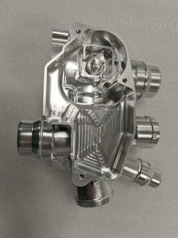
Machined aluminum parts are widely used in automotive, electronics, medical equipment, industrial machinery, aerospace systems and prototype development. Aluminum is lightweight, easy to machine and available in many useful grades.
However, good CNC machining is not only about cutting the part to shape. Tight tolerances, surface finish, part distortion and post-processing can all affect final quality.
Therefore, engineers should define the real functional requirements before machining starts. A tolerance that is too tight increases cost. Meanwhile, a poor surface finish may affect sealing, assembly, appearance or coating performance.
At Fentor Mold, we manufacture CNC machined components and also support mold and plastic-part projects. This allows us to review machining requirements from both a production and assembly perspective.
What Are Machined Aluminum Parts?
Machined aluminum parts are components produced by removing material from aluminum stock with CNC equipment.
Common processes include:
- CNC milling
- CNC turning
- Drilling
- Boring
- Tapping
- Reaming
- Grinding
- EDM for selected features
Depending on geometry, one part may require several machining operations.
Common aluminum grades include:
- 6061
- 6063
- 6082
- 7075
- 2024
- 5052
Among them, 6061 is one of the most common choices because it offers a good balance of machinability, strength, corrosion resistance and cost.
7075 provides higher strength, although it usually costs more.
Why Tolerances Matter for Machined Aluminum Parts
Tolerance controls how much a finished dimension may vary from the nominal design value.
For example, if a drawing specifies:
20.00 ±0.05 mm
the acceptable size is between 19.95 mm and 20.05 mm.
This sounds simple. However, tighter tolerances require more process control.
They may require:
- More precise CNC equipment
- Better workholding
- Additional machining passes
- Slower cutting
- More inspection
- Temperature control
- Tool-wear monitoring
As a result, tighter tolerance usually means higher cost.
Therefore, the drawing should apply tight tolerances only where they affect function.
Typical Tolerances for Machined Aluminum Parts
There is no single tolerance that applies to every CNC aluminum component.
The achievable result depends on:
- Part size
- Aluminum grade
- Geometry
- Wall thickness
- Machine accuracy
- Tool condition
- Fixture design
- Inspection method
For many standard CNC parts, general tolerances around ±0.05 mm to ±0.10 mm may be practical.
However, certain critical features can require tighter tolerances.
Examples include:
- Bearing bores
- Dowel holes
- Seal surfaces
- Precision locating faces
- Mating features
- Shaft fits
For these features, tolerances may need to reach ±0.01 mm or tighter depending on the application.
However, designers should not apply this level of tolerance to the entire part unless necessary.
How to Control Tolerances in Machined Aluminum Parts
Tolerance control starts before the CNC machine begins cutting.
Use Functional Tolerances
The first step is to identify which dimensions really control product function.
For example, a mounting hole position may need tight control. A non-functional outer surface may not.
Therefore, drawings should separate:
- Critical dimensions
- Assembly dimensions
- Cosmetic dimensions
- Reference dimensions
This makes machining easier and reduces unnecessary cost.
Avoid Over-Tolerancing
Over-tolerancing is one of the most common CNC design mistakes.
A drawing may specify ±0.01 mm everywhere even though only two or three dimensions actually require that accuracy.
This creates several problems:
- Higher machining cost
- Longer inspection time
- Higher rejection risk
- More complicated fixturing
- Longer lead time
A better approach is to tighten only the important dimensions.
Machined Aluminum Parts and Thermal Expansion
Aluminum expands and contracts with temperature.
Therefore, dimensional inspection can change slightly depending on part temperature.
This becomes more important when tolerances are very tight.
For example, a part measured immediately after machining may still be warm. If it is inspected before stabilizing, the measurement may not represent its final room-temperature size.
For high-precision components, manufacturers may allow the part to cool before final inspection.
Temperature-controlled inspection rooms may also be used for demanding applications.
Thin Walls Can Affect Machining Tolerance
Thin aluminum walls are easy to deform.
During machining, cutting forces may push the wall away from the tool.
After the tool moves away, the wall can spring back.
As a result, the final dimension may differ from the programmed toolpath.
Thin walls can also distort because of:
- Internal material stress
- Fixture pressure
- Heat
- Uneven stock removal
Therefore, very thin sections often require special machining strategies.
These may include:
- Multiple light finishing cuts
- Balanced material removal
- Reduced clamping force
- Support fixtures
- Lower cutting forces
Workholding Affects Machined Aluminum Parts
A good CNC machine cannot produce stable tolerances if the workholding system distorts the part.
Clamps must hold the aluminum securely without bending it.
This is especially important for:
- Thin plates
- Long parts
- Large housings
- Thin-wall structures
If the fixture pressure is too high, the part may deform during machining.
Then, after the clamps are released, the component may spring back.
Therefore, fixture design is part of tolerance control.
Our components manufacturing service includes machining support for precision mold components, prototypes and custom metal parts.
Tool Wear and CNC Accuracy
Cutting tools gradually wear during machining.
As the cutting edge changes, part dimensions may also change.
For high-volume production, manufacturers should monitor tool wear and replace tools before dimensions move outside the tolerance range.
Common methods include:
- Tool-life control
- Scheduled tool replacement
- In-process measurement
- First-piece inspection
- Periodic sampling
For highly critical machined aluminum parts, stable tooling is just as important as machine accuracy.
What Is Surface Finish on Machined Aluminum Parts?
Surface finish describes the texture and quality of a machined surface.
It can affect:
- Appearance
- Friction
- Sealing
- Coating
- Wear
- Fatigue
- Assembly
Surface finish is often measured as surface roughness.
A common parameter is Ra, or arithmetic average roughness.
A lower Ra value means a smoother surface.
However, a smoother surface is not always necessary.
For many parts, standard CNC machining already provides an acceptable finish.
Common Surface Finish Levels
Typical machined finishes may vary depending on process and tool condition.
For example:
| Surface Requirement | Typical Use |
|---|---|
| Standard machined | General structural parts |
| Fine machined | Visible or fitting surfaces |
| Polished | Cosmetic or low-friction surfaces |
| Ground | Precision flat or dimensional surfaces |
| Bead blasted | Uniform matte appearance |
| Anodized | Protection and appearance |
If a drawing requires a specific Ra value, the manufacturer should confirm whether the selected machining method can achieve it consistently.
How to Improve Surface Finish
Several factors influence the finish of CNC machined aluminum.
Cutting Tool Condition
A sharp cutting edge usually produces a cleaner surface.
Worn tools can create:
- Tool marks
- Burrs
- Rough surfaces
- Dimensional variation
Therefore, tool condition must be monitored carefully.
Feed Rate
Higher feed rates may increase machining speed.
However, they can also create more visible tool marks.
For cosmetic areas, a slower finishing pass may improve the appearance.
Tool Geometry
Tool diameter, flute design and cutting angle all influence surface quality.
The correct tool also helps reduce chatter.
Machine Rigidity
Machine vibration can leave repetitive marks on the surface.
Therefore, stable workholding and proper cutting conditions are important.
Machined Aluminum Parts and Anodizing
Anodizing is one of the most common surface treatments for aluminum.
It improves:
- Corrosion resistance
- Surface hardness
- Wear resistance
- Appearance
Common finishes include:
- Clear anodizing
- Black anodizing
- Colored anodizing
- Hard anodizing
However, anodizing can also affect final dimensions.
This is especially important for:
- Precision bores
- Threads
- Sliding fits
- Bearing locations
- Tight assemblies
Therefore, engineers should indicate clearly whether the drawing dimensions apply before or after anodizing.
Does Anodizing Change Dimensions?
Yes.
Anodizing creates an oxide layer on the aluminum surface.
Part of this layer grows outward from the original surface.
Therefore, dimensions can change slightly after finishing.
For general parts, this difference may not matter.
However, it can become important when a feature has a very tight tolerance.
Critical features may require:
- Masking
- Post-machining
- Allowance before anodizing
- Special inspection requirements
The machining supplier should know the final finishing process before finalizing CNC dimensions.
Bead Blasting Before Anodizing
Bead blasting is often used before anodizing to create a uniform matte appearance.
This can reduce visible machining marks.
However, the blasting process can also slightly change the surface texture and edge definition.
Therefore, critical sealing or precision mating surfaces may need protection.
Cosmetic requirements should also be clearly defined because different blasting media can produce different appearances.
Burr Control on Machined Aluminum Parts
Aluminum can form burrs along machined edges and drilled holes.
Burrs can interfere with:
- Assembly
- Sealing
- Electrical contact
- Product appearance
- Operator safety
Therefore, drawings often include edge requirements such as:
- Break sharp edges
- Deburr all edges
- Add chamfers
- Add radii
However, edge finishing should also be controlled.
Excessive manual deburring can damage tight-tolerance features.
How Surface Finish Affects Assembly
Surface finish can directly affect how two components fit together.
For example, a very rough bore may increase friction.
A rough sealing face can create leakage.
Meanwhile, an excessively smooth surface may not always be necessary.
Therefore, surface requirements should be based on actual function.
Common critical areas include:
- O-ring grooves
- Seal faces
- Bearing seats
- Sliding surfaces
- Precision locating faces
Inspection Methods for Machined Aluminum Parts
Inspection depends on the tolerance and geometry.
Common tools include:
- Calipers
- Micrometers
- Height gauges
- Bore gauges
- Pin gauges
- Thread gauges
- Optical systems
- CMM
A CMM is often used for parts with complex geometry or precise positional requirements.
For example, it can verify:
- Hole positions
- Flatness
- Perpendicularity
- Parallelism
- Profiles
- Datum relationships
However, not every dimension requires CMM inspection.
Selecting the correct inspection method helps control both quality and cost.
GD&T for Machined Aluminum Parts
Geometric Dimensioning and Tolerancing, or GD&T, can provide better control than simple plus-and-minus dimensions.
GD&T may specify:
- Flatness
- Parallelism
- Perpendicularity
- Position
- Profile
- Runout
This is useful because a part may meet individual dimensional tolerances but still fail during assembly.
For example, a hole may have the correct diameter but be in the wrong position.
Therefore, GD&T helps communicate functional requirements more clearly.
Common Problems With CNC Machined Aluminum Parts
Several issues frequently appear during production.
Dimensional Variation
Possible causes include:
- Tool wear
- Fixture movement
- Heat
- Thin-wall deformation
- Machine calibration
Poor Surface Finish
Possible causes include:
- Dull tools
- Excessive feed rate
- Machine vibration
- Poor chip evacuation
Warpage
Large or thin aluminum components may distort after machining.
Balanced stock removal and proper fixturing can help reduce this risk.
Burrs
Sharp edges and drilled holes may require secondary deburring.
Color Variation After Anodizing
Different aluminum batches or surface conditions can produce slight color differences.
Therefore, cosmetic anodized components may require tighter material and finishing controls.
Prototype Machined Aluminum Parts
CNC machining is highly suitable for prototype aluminum parts because it does not require expensive production tooling.
It can be used for:
- Functional prototypes
- Assembly testing
- Low-volume production
- Engineering validation
- Fixtures
- Test components
This makes CNC machining useful before a project moves into larger-scale manufacturing.
For early-stage projects, you can also review our prototype injection molding service when plastic prototypes are needed alongside metal components.
Machining Aluminum Parts for Injection Molds
Aluminum machining is also common in mold-related projects.
Typical machined items include:
- Prototype mold inserts
- Fixtures
- Jigs
- Inspection tools
- Support components
- Trial tooling
However, production mold components often use tool steel rather than aluminum because of higher wear and pressure requirements.
You can learn more about tooling development from our injection mold manufacturing page.
How to Reduce Machined Aluminum Part Cost
The easiest way to reduce machining cost is not always to choose a cheaper supplier.
Good design can reduce cost before quoting.
Consider the following:
- Avoid unnecessary ±0.01 mm tolerances
- Standardize hole sizes
- Avoid extremely deep pockets
- Reduce thin-wall areas
- Allow practical corner radii
- Minimize setups
- Avoid excessive cosmetic finishing
- Clearly identify critical dimensions
As a result, the supplier can machine the part faster and with lower rejection risk.
What Should You Send to a CNC Machining Supplier?
For accurate quotation and production, provide:
- 3D CAD
- 2D drawing
- Aluminum grade
- Quantity
- Tolerance requirements
- Surface finish
- Anodizing requirements
- Color requirements
- Inspection requirements
- Critical dimensions
If only a 3D file is supplied, some important tolerance information may be missing.
Therefore, a 2D drawing is still valuable for precision machined aluminum parts.
Final Thoughts
Producing high-quality machined aluminum parts requires more than accurate CNC equipment.
Tolerance control depends on part geometry, workholding, tool condition, temperature, machining sequence and inspection.
Surface finish also needs careful planning. Cutting parameters, deburring and post-processing such as bead blasting or anodizing can all change the final result.
Therefore, engineers should clearly identify critical dimensions, functional surfaces and post-processing requirements before machining begins.
By defining only the tolerances and finishes that truly matter, manufacturers can achieve better part quality while also controlling machining cost and lead time.