
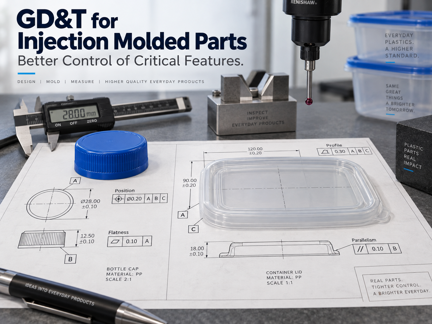
GD&T for Injection Molded Parts helps control the shape, position, and relation of important features on a plastic part.
A normal size tolerance only tells us how large or small a feature can be.
However, many plastic parts also need control of:
- Flatness
- Position
- Parallelism
- Perpendicularity
- Profile
- Concentricity
- Runout
These controls matter because a part can meet its basic size and still fail in assembly.
For example, a hole diameter may be correct. However, if the hole position shifts, the mating part may not fit.
Therefore, GD&T for Injection Molded Parts should focus on features that affect real product function.
What Is GD&T for Injection Molded Parts?
GD&T means Geometric Dimensioning and Tolerancing.
It defines how much a feature can vary in shape, position, or direction.
GD&T for Injection Molded Parts is especially useful because plastic parts do not behave like machined metal parts.
Plastic can:
- Shrink
- Warp
- Bend
- Relax after molding
- Change with temperature
- Change with moisture
As a result, a part may move slightly after it leaves the mold.
Therefore, GD&T should consider both design intent and real molding behavior.
Why GD&T for Injection Molded Parts Matters
Many plastic parts work inside an assembly.
The key question is not only:
“Is the part within size tolerance?”
Instead, the better question is:
“Will the part still fit and work correctly?”
For example, a housing may need:
- Two mounting holes in the right position
- A flat sealing surface
- A connector face at the correct angle
- A cover that sits evenly
- A shaft hole aligned with another feature
If these relationships are not controlled, assembly problems may appear.
Therefore, GD&T for Injection Molded Parts can make the drawing much clearer.
GD&T for Injection Molded Parts Should Start With Function
Not every feature needs a geometric tolerance.
Too many GD&T requirements can make the drawing harder to read.
They can also make the part harder to inspect.
Instead, focus on features that affect:
- Assembly
- Sealing
- Motion
- Alignment
- Positioning
- Appearance
- Function
For example, a decorative rib may not need tight position control.
However, a screw boss that must match a mating hole may need it.
Therefore, the first step is to understand which features truly matter.
GD&T for Injection Molded Parts Depends on Good Datum Selection
GD&T depends heavily on datums.
A datum is a reference used to locate or orient other features.
Typical datums may be:
- A flat mounting surface
- A center plane
- A large hole
- A mating face
- A sealing surface
If the datum is poorly chosen, inspection results may become confusing.
For example, a warped cosmetic surface is not a good main datum.
Instead, choose a stable and functional surface.
For this reason, datum selection is a key part of GD&T for Injection Molded Parts.
GD&T for Injection Molded Parts: Flatness Control
Flatness is one of the hardest items to control in plastic parts.
This is because plastic can warp after molding.
Possible causes include:
- Uneven wall thickness
- Uneven cooling
- Poor gate location
- Internal stress
- Material shrinkage
- Fiber direction
For example, a large flat housing may look good right after molding.
However, one corner may lift after cooling.
As a result, flatness can fail even when thickness and outer dimensions are correct.
Therefore, flatness should be set based on real function.
A sealing surface may need tighter control than a cosmetic surface.
GD&T for Injection Molded Parts: Position Tolerance
Position tolerance is often used for:
- Holes
- Bosses
- Pins
- Inserts
- Connector features
- Mounting points
In many cases, it is more useful than separate X and Y tolerances.
For example, a screw boss may be 50 mm from one edge and 30 mm from another.
If both dimensions use separate ± tolerances, the true allowed location may be unclear.
Position tolerance creates a clear zone around the target location.
Therefore, it often describes assembly needs better.
Hole Position Can Change Because of Shrinkage
Hole position is not controlled only by mold machining.
Plastic shrinkage also affects the final part.
For example, two holes may be correct in the steel.
However, after molding, the distance between them may change.
This may happen because of:
- Uneven shrinkage
- Gate direction
- Cooling
- Material type
- Glass fiber direction
Therefore, GD&T for Injection Molded Parts should be verified on real molded samples, not only on the mold.
GD&T for Injection Molded Parts: Profile Control
Profile tolerance is useful for curved or complex surfaces.
Typical examples include:
- Exterior housings
- Large covers
- Automotive trim
- Cosmetic panels
- Sealing surfaces
- Complex mating areas
Instead of checking many separate dimensions, profile can control the whole surface.
As a result, the drawing may become easier to understand.
However, profile can also be hard to control.
Warpage, shrinkage, and sink marks can all affect the surface.
Therefore, profile tolerance should be set carefully.
Parallelism Can Affect Assembly
Parallelism matters when two surfaces must stay aligned.
Examples include:
- Two mounting faces
- A cover and base
- A sliding feature
- A sealing plate
A part may have the correct thickness.
However, if the two surfaces are not parallel, assembly may still fail.
This can happen when one side cools faster than the other.
Therefore, cooling and part design both affect parallelism.
Perpendicularity Can Be Difficult on Tall Features
Tall bosses, ribs, or walls may need perpendicularity control.
However, these features can move during molding.
Possible causes include:
- Weak feature design
- Uneven cooling
- High injection pressure
- Core pin movement
- Ejection force
For example, a tall boss may lean slightly.
The diameter may still be correct.
However, the screw can enter at an angle.
Therefore, perpendicularity may matter more than diameter alone.
Concentricity and Runout Need Careful Use
Concentricity and runout are more common on round parts.
Examples include:
- Rotating plastic parts
- Cylindrical housings
- Bushings
- Sleeves
- Gear-related parts
However, these controls should not be added without a clear reason.
They can increase inspection difficulty.
In many cases, position or profile may describe the function more clearly.
Therefore, use the simplest control that matches the real need.
Mold Accuracy Is Only Part of GD&T Control
A precise mold is necessary.
However, accurate mold machining alone does not guarantee good GD&T results.
Plastic behavior also matters.
For example, a core insert can be machined very accurately.
Still, the final part may warp after cooling.
Therefore, GD&T for Injection Molded Parts depends on:
- Mold accuracy
- Part design
- Material
- Gate location
- Cooling
- Process settings
- Ejection
- Measurement method
At Fentor Mold, our Injection Mold service combines mold design, machining, trial, correction, and final part checks.
GD&T for Injection Molded Parts Depends on Cooling
Cooling is one of the main causes of part movement.
If cooling is uneven, the part may:
- Warp
- Twist
- Bend
- Lose flatness
- Move hole positions
- Change profile
Therefore, cooling design should consider the features with GD&T requirements.
For example, a sealing face may need more even cooling than a non-functional area.
In addition, large cores may need special cooling.
Stable mold temperature also helps improve repeatability.
Gate Location Can Change Position and Profile
Gate location affects flow and packing.
As a result, it can influence:
- Shrinkage
- Warpage
- Weld lines
- Fiber direction
- Internal stress
For example, a gate on one side may create more shrinkage in one direction.
Therefore, the part may twist after cooling.
This can directly affect position and profile tolerances.
For complex parts, Moldflow can help compare gate options before mold manufacturing.
GD&T for Injection Molded Parts Depends on Material Stability
Different plastics behave differently.
For example:
- ABS is usually easier to control
- PC+ABS can offer good dimensional stability
- PA can change with moisture
- POM has higher shrinkage
- PBT can be stable but still needs good drying
- Glass-filled materials can show directional shrinkage
Therefore, material choice should be considered before very tight GD&T limits are set.
A tolerance that is easy in one material may be difficult in another.
Glass Fiber Can Change Part Shape
Glass-filled materials can improve strength and stiffness.
However, they can also make shrinkage more directional.
The part may shrink more in one direction than another.
As a result:
- Flatness may change
- Hole positions may move
- Profile may change
- Warpage may increase
Therefore, fiber direction should be considered in part design and gate layout.
This is especially important for large or long parts.
Ejection Can Affect Geometric Accuracy
A part may leave the cavity in good shape.
However, poor ejection can deform it.
Possible problems include:
- Bending
- Whitening
- Twist
- Local sink
- Boss movement
Therefore, ejector pins should be placed in strong areas.
The part also needs enough draft.
For some parts, balanced ejection is critical to final GD&T results.
GD&T for Injection Molded Parts Needs the Right Measurement Method
A good drawing still needs a good inspection method.
Different controls need different tools.
These may include:
- CMM
- Vision measurement
- Height gauge
- Surface plate
- Custom fixture
- Optical scanner
However, measurement setup matters.
If the part is forced flat during inspection, the result may look good.
In reality, the free part may still be warped.
Therefore, the inspection method should match the real product condition.
Plastic Parts May Need Conditioning Before Measurement
Plastic dimensions can change after molding.
This is common with:
- PA
- POM
- PP
- Glass-filled materials
- Large parts
Therefore, measurement timing should be controlled.
For example, parts may be measured:
- After full cooling
- After 24 hours
- After moisture conditioning
- At a defined temperature
The exact method depends on the product.
However, the buyer and supplier should use the same condition.
Otherwise, the results may not match.
GD&T for Injection Molded Parts Should Be Checked Across Several Parts
One good part is not enough.
Several molded parts should be measured.
This helps show whether the process is stable.
For critical features, check:
- Average result
- Variation
- Cavity differences
- Trend over time
If one feature stays close to the limit, future production may become risky.
Therefore, GD&T for Injection Molded Parts should also be reviewed as part of process stability.
Our article on Injection Molding Cpk explains how process capability can help check critical dimensions over time.
GD&T for Injection Molded Parts in Multi-Cavity Molds
Different cavities may produce slightly different geometry.
Possible causes include:
- Gate variation
- Cooling differences
- Insert dimensions
- Venting
- Local temperature
Therefore, parts should remain traceable by cavity.
If all samples are mixed together, one weak cavity may be hidden.
Our article on Multi-Cavity Injection Molding explains why cavity tracking is useful.
Common GD&T Problems in Injection Molded Parts
Flatness Failure
Possible causes:
- Uneven cooling
- Uneven wall thickness
- Poor gate position
- Internal stress
Position Failure
Possible causes:
- Shrinkage
- Mold insert position
- Warpage
- Core movement
Profile Failure
Possible causes:
- Local sink
- Warpage
- Uneven packing
- Material shrinkage
Perpendicularity Failure
Possible causes:
- Tall feature movement
- Core pin movement
- Ejection force
- Poor cooling
Parallelism Failure
Possible causes:
- Uneven cooling
- Part distortion
- Poor support
- Shrinkage difference
Therefore, the correct solution depends on the real cause.
Do not modify mold steel before checking the molding process and part condition.
Better GD&T Control Starts With Realistic Tolerances
Tighter tolerance is not always better.
Very tight limits can increase:
- Mold cost
- Trial time
- Inspection cost
- Scrap rate
- Production risk
Therefore, tolerance should match the actual function.
If a feature does not affect assembly or performance, it may not need tight geometric control.
As a result, the drawing becomes easier to follow.
Production also becomes easier to control.
Fentor Mold Approach to Critical Plastic Features
At Fentor Mold, we review critical features before mold manufacturing.
The focus is not only on the drawing value.
Instead, we also look at how the feature works in the final assembly.
This helps identify:
- Important datums
- Critical positions
- Sealing surfaces
- Flatness risks
- Warpage risks
- Measurement methods
Our Injection Molding Production service then helps verify these features under stable molding conditions before regular production.
Final Thoughts
GD&T for Injection Molded Parts helps control more than basic size.
It defines whether important features are in the correct shape, position, and relation.
The most common controls include:
- Flatness
- Position
- Profile
- Parallelism
- Perpendicularity
However, plastic parts can shrink, warp, and change after molding.
Therefore, good GD&T control depends on more than mold machining.
It also depends on part design, material, cooling, gate location, process stability, and measurement.
At Fentor Mold, we prefer realistic tolerances based on the actual product function.
A good plastic part should not only match the drawing.
Instead, it should fit, assemble, and work correctly in real production.