
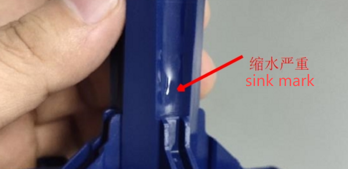
Why Do Thick-Wall PC Parts Have Sink Marks?
Sink marks are shallow depressions that appear on the surface of injection molded parts.
They are especially common on thick-wall PC parts.
The main reason is simple: thick plastic takes longer to cool and shrinks more as it solidifies.
When the inside of the part shrinks, it can pull the outer surface inward and create a visible depression.
1. Avoid Unnecessary Thick Walls
The best solution is to reduce excessive wall thickness.
A thick solid section takes a long time to cool and creates more shrinkage.
If strength is required, consider using:
- Ribs
- Bosses
- Structural supports
- Hollow sections
A well-designed rib structure can provide strength without creating a large solid area.
2. Keep Wall Thickness More Uniform
Large differences in wall thickness can create uneven cooling.
For example, a thin wall next to a very thick section will cool at different speeds.
The thick section continues shrinking after the surface has already solidified.
This can pull the surface inward.
A more uniform wall thickness helps reduce this problem.
3. Pay Attention to Rib Thickness
Ribs are useful, but they can also create sink marks.
A thick rib connected directly to a cosmetic wall can produce a visible depression on the opposite surface.
As a general design principle, ribs should not be unnecessarily thick.
For appearance-critical PC parts, the rib structure should be reviewed together with the cosmetic surface.
4. Improve Cooling
Cooling is critical for thick-wall PC parts.
A thick section needs enough cooling time to solidify properly.
If the cooling channels are too far away or poorly arranged, the core of the part can remain hot for too long.
The result may be:
- Sink marks
- Warpage
- Longer cycle time
- Dimensional instability
A balanced cooling system helps the part cool more evenly.
Our injection mold manufacturing service includes cooling system design based on the product structure.
5. Maintain Sufficient Holding Pressure
Holding pressure helps compensate for material shrinkage while the gate remains open.
If holding pressure is too low, the material inside the thick section may continue to shrink without enough additional material entering the cavity.
This can increase sink marks.
However, simply using very high holding pressure is not always the answer.
The correct holding pressure and holding time depend on the material, gate size, wall thickness, and product structure.
6. Check the Gate Size
The gate must remain open long enough to provide packing pressure to the cavity.
If the gate freezes too early, additional material cannot enter the thick section.
The internal material then continues to shrink, increasing the risk of sink marks.
For thick-wall PC parts, gate size and location should be checked carefully.
7. Use Mold Flow Analysis for Difficult Parts
Large thick-wall PC parts can be difficult to predict through experience alone.
Mold flow analysis can help identify:
- Thick sections
- Cooling problems
- Filling pressure
- Gate freeze time
- Potential sink areas
- Warpage risk
This allows the mold designer to make changes before machining begins.
Practical Ways to Reduce Sink Marks
A good approach is:
- Reduce unnecessary wall thickness.
- Keep wall thickness as uniform as possible.
- Avoid overly thick ribs and bosses.
- Improve cooling around thick sections.
- Optimize holding pressure and time.
- Select a suitable gate size and location.
- Use mold flow analysis for complex products.
Final Thoughts
For thick-wall PC parts, sink marks are usually caused by internal shrinkage and uneven cooling.
Increasing holding pressure may help, but it cannot fully solve a poor product design.
The best approach is to start with the wall thickness, rib structure, gate design, and cooling system.
Good mold design can reduce sink marks, shorten molding trials, and improve dimensional stability.
Fentormold provides injection molding production and mold manufacturing services for PC and other engineering plastics.
For more practical injection molding solutions, visit the Fentormold blog.