
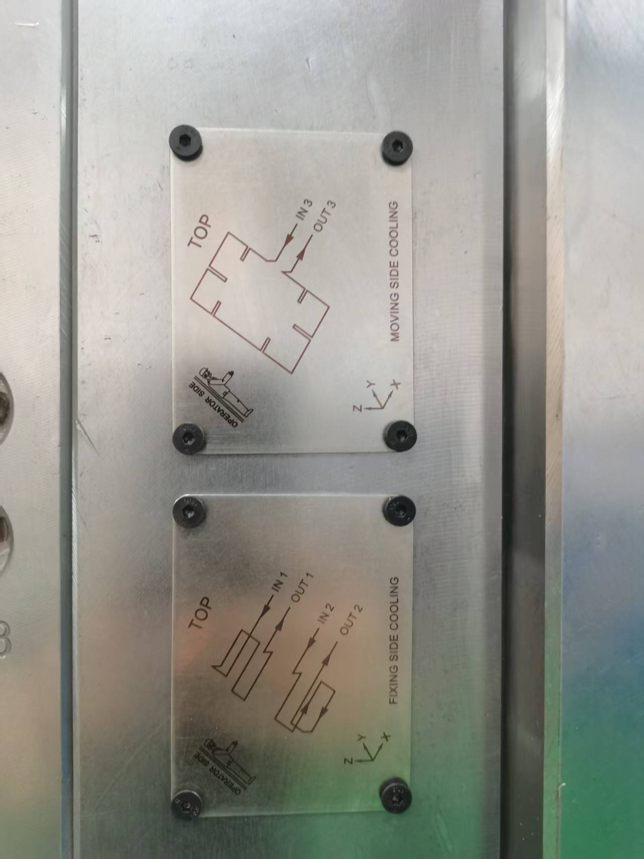
Injection mold cooling circuit identification is easy to overlook, but poor identification can create serious production problems.
A mold may contain many water lines for the cavity, core, sliders, lifters, inserts, and hot runner system. If the inlet and outlet connections are mixed up, cooling performance can change immediately.
As a result, the mold may develop uneven temperatures, longer cycle times, unstable dimensions, or local overheating.
In more serious cases, technicians may connect the wrong circuit entirely. Therefore, clear cooling circuit identification should be completed before mold trial, shipment, and production.
At Fentor Mold, we treat cooling identification as part of mold delivery preparation rather than a simple labeling job.
What Is Injection Mold Cooling Circuit Identification?
Injection mold cooling circuit identification means clearly marking every cooling inlet and outlet on the mold.
Typical identification may include:
- Circuit number
- Water inlet
- Water outlet
- Cavity side
- Core side
- Slider cooling
- Insert cooling
- Hot runner cooling
- Special temperature-control circuit
For example, a mold may use:
IN1 → OUT1
IN2 → OUT2
IN3 → OUT3
This simple numbering system helps technicians connect each circuit correctly.
However, large molds can have 10, 20, or even more separate cooling lines. Therefore, numbering alone may not always be enough.
The mold drawing and cooling circuit diagram should match the physical markings on the mold.
Why Injection Mold Cooling Circuit Identification Matters
Incorrect cooling connections can change the thermal balance of the mold.
This is especially important when different areas need different cooling conditions.
For example, the core may require stronger cooling than the cavity. A large slider may also have its own separate water circuit.
If technicians connect these circuits incorrectly, the mold may not operate as originally designed.
Common results include:
| Connection Error | Possible Result |
|---|---|
| Inlet and outlet mixed | Unstable or reduced flow |
| Wrong circuit connected | Incorrect cooling area |
| Two circuits connected together | Uneven water distribution |
| One circuit left disconnected | Local overheating |
| Cooling line connected to wrong controller | Wrong mold temperature |
| Flow direction reversed | Poor cooling in some structures |
| Circuit number missing | Longer setup time |
Therefore, good identification reduces both setup errors and troubleshooting time.
Common Injection Mold Cooling Circuit Identification Problems
Several problems appear repeatedly during mold trial and production.
Missing Circuit Numbers
The simplest problem is having no clear number beside the water connector.
Technicians then need to check drawings or manually test every line.
This wastes time and increases the risk of connection errors.
Numbers Do Not Match the Drawing
Sometimes the mold is marked correctly, but the cooling diagram uses different numbers.
This creates confusion during mold transfer.
For example, the mold may show IN3, while the drawing identifies the same circuit as C2.
Therefore, the physical mold and documentation must use the same identification system.
Labels Are Difficult to Read
Paint markers and temporary stickers may disappear during cleaning or production.
As a result, identification becomes unclear after several months.
For long-term molds, permanent engraving or durable metal labels are more reliable.
Injection Mold Cooling Circuit Identification for IN and OUT
Every circuit should clearly show the inlet and outlet.
A common method is:
IN1OUT1IN2OUT2
This makes connection faster.
However, simply numbering both ends as 1 may create confusion.
For example:
1 → 1
does not clearly show which side should receive the incoming water.
Therefore, using IN and OUT is better.
For critical circuits, flow direction arrows can also help.
Does Cooling Flow Direction Matter?
In many simple drilled water channels, reversing the flow may not cause an immediate problem.
However, this does not mean flow direction is always unimportant.
Some cooling structures work better with a specific direction.
Examples include:
- Baffles
- Bubblers
- Spiral cooling inserts
- Long narrow circuits
- Series-connected channels
- High-point air removal
- Temperature-sensitive inserts
For these structures, wrong flow direction can reduce cooling efficiency.
Therefore, injection mold cooling circuit identification should include flow direction when the circuit design depends on it.
Avoid Connecting the Wrong Cooling Circuit
A common mistake happens when several connectors are close together.
For example, the cavity side may contain six water connectors in one row.
Without clear identification, technicians may connect:
IN1 → OUT2
instead of:
IN1 → OUT1
The water may still flow, so the error is not always obvious.
However, the real cooling path is now incorrect.
As a result, one circuit may receive too much flow while another gets little or no water.
Therefore, every inlet should have a matching outlet number.
Series and Parallel Cooling Connections
Cooling circuits can be connected in different ways.
Series Connection
In a series connection, water flows through one area and then continues into another.
The advantage is simple piping.
However, the water temperature rises as it moves through the circuit.
Therefore, the last area may receive warmer water.
Parallel Connection
In a parallel system, several circuits receive water separately.
This can provide more even cooling.
However, flow balance becomes more important.
If one circuit has much lower resistance, it may receive more water than the others.
For this reason, the cooling diagram should clearly show whether circuits should be connected in series or parallel.
Do not leave this decision to the molding technician after the mold arrives.
Injection Mold Cooling Circuit Identification for Sliders and Lifters
Sliders and lifters often need separate cooling.
These components can generate local hot spots because they are surrounded by steel and may have limited space for water channels.
For example, a large slider may use:
SL1-IN → SL1-OUT
A second slider may use:
SL2-IN → SL2-OUT
This is clearer than continuing with a long list of general numbers.
For complicated molds, component-based identification can reduce errors.
Possible abbreviations include:
CAV– cavityCORE– coreSL– sliderLF– lifterINS– insertHR– hot runner
However, the abbreviations should also appear in the cooling diagram.
Keep Hot Runner Cooling Separate
Hot runner cooling connections should be clearly separated from normal mold cooling.
For example, some molds use water cooling around:
- Hot runner plates
- Nozzle areas
- Hydraulic cylinders
- Valve pin actuators
Connecting these circuits incorrectly may affect hot runner performance.
Therefore, they should have unique labels.
For example:
HR-IN / HR-OUT
is much clearer than using another general circuit number.
This is especially important when the mold has many connectors close together.
Use a Cooling Circuit Diagram
A physical label tells the technician where to connect a hose.
However, a cooling diagram explains where the water actually goes.
Therefore, both are useful.
A good cooling diagram should show:
- Circuit numbers
- IN and OUT positions
- Flow direction
- Cavity/core location
- Slider or insert cooling
- Series connections
- Parallel connections
- Special temperature requirements
The drawing should be simple enough to understand quickly.
For complex molds, a color-coded diagram may also help during internal use. However, the printed version should still remain clear if printed in black and white.
Injection Mold Cooling Circuit Identification Before Mold Trial
Cooling identification should be checked before the first mold trial.
Do not wait until the mold reaches production.
Before trial, technicians should confirm:
- Every connector has an ID.
- Each IN has a matching OUT.
- The drawing matches the mold.
- Water flows through every circuit.
- No circuit is blocked.
- Flow direction is correct where required.
- No leakage appears.
This stage is also a good time to perform an injection mold cooling test.
If the mold is difficult to connect during the first trial, the customer will probably face the same problem later.
Therefore, the final identification should be improved before shipment.
Check Cooling Flow, Not Just Labels
Correct labels do not guarantee correct cooling.
A circuit may be identified correctly but still have poor flow.
Possible causes include:
- Blocked channel
- Rust
- Metal chips
- Small connector
- Sharp internal turn
- Incorrect baffle position
- Long circuit
- Water leakage
Therefore, technicians should check actual flow.
For critical molds, a flow meter can provide useful data.
This allows the team to compare different circuits and identify abnormal resistance.
At Fentor Mold, cooling checks are normally combined with mold trial observations because temperature problems often appear only after continuous cycling.
Avoid Temporary Marking Methods
Temporary handwritten marks are useful during mold assembly.
However, they are not ideal for final delivery.
Oil, mold cleaner, water, and handling can remove them.
For permanent injection mold cooling circuit identification, better options include:
- Laser engraving
- Mechanical engraving
- Metal identification plates
- Permanent stamped numbers
The marking should remain readable after long-term production and maintenance.
In addition, the identification should not be placed where clamps, hoses, or machine components can easily cover it.
Standardize the Identification System
Using the same identification method on every mold makes production easier.
For example:
| Cooling Area | Suggested Identification |
|---|---|
| Cavity circuit 1 | CAV-IN1 / CAV-OUT1 |
| Cavity circuit 2 | CAV-IN2 / CAV-OUT2 |
| Core circuit 1 | CORE-IN1 / CORE-OUT1 |
| Slider 1 | SL1-IN / SL1-OUT |
| Slider 2 | SL2-IN / SL2-OUT |
| Hot runner | HR-IN / HR-OUT |
The exact format can vary.
However, consistency is more important than the specific naming style.
If every project uses a different system, technicians must relearn the connection method each time.
Injection Mold Cooling Circuit Identification During Mold Transfer
Cooling identification becomes even more important when a mold moves to another supplier.
The new molding factory may have no knowledge of the original mold design.
Without clear labels, technicians may need to trace every cooling path manually.
This adds setup time and increases risk.
Therefore, a transferred mold should ideally include:
- Cooling circuit diagram
- Connector identification
- Mold drawings
- Recommended water temperature
- Required flow information
- Special cooling notes
Clear documentation can save hours during installation.
How Connection Errors Affect Part Quality
Cooling connection errors can directly affect molded parts.
Typical problems include:
- Warpage
- Sink marks
- Dimensional variation
- Long cycle time
- Uneven shrinkage
- Hot spots
- Surface gloss differences
- Difficult demolding
For example, if one core circuit is accidentally disconnected, that area may run hotter than the rest of the mold.
As a result, the plastic cools more slowly and shrinks differently.
The defect may look like a material or molding parameter problem.
However, the real cause is simply an incorrect cooling connection.
Cooling Circuit Identification Checklist
Before shipping or starting production, use a simple checklist.
| Inspection Item | Check |
|---|---|
| Every connector marked | Yes / No |
| IN and OUT identified | Yes / No |
| Circuit numbers match | Yes / No |
| Drawing matches mold | Yes / No |
| Flow direction shown | Yes / No |
| Slider circuits identified | Yes / No |
| Hot runner circuit separated | Yes / No |
| Water flow tested | Yes / No |
| Leakage checked | Yes / No |
| Labels are permanent | Yes / No |
This takes little time.
However, it can prevent many avoidable production problems.
Final Thoughts
Injection mold cooling circuit identification is a small detail with a large effect on production reliability.
A mold can have an excellent cooling design, but that design cannot work correctly if technicians connect the circuits incorrectly.
Therefore, every inlet and outlet should have clear, permanent identification.
The physical markings should also match the cooling diagram.
For complex molds, cavity, core, slider, lifter, insert, and hot runner circuits should be separated clearly.
At Fentor Mold, we prefer to complete cooling identification and connection checks before mold shipment. This makes mold setup easier and reduces unnecessary troubleshooting after the mold reaches production.