
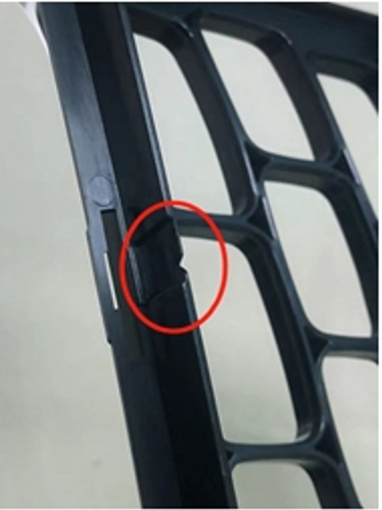
Injection mold gas traps can cause burn marks, short shots, and poor surface quality. Air becomes trapped when it cannot escape from the mold cavity. As hot plastic fills the mold, the trapped gas heats up. This can leave dark marks on the finished part.
Burn marks often appear near the end of the flow path, inside deep ribs, or around narrow pockets. Poor venting is a common cause. Still, the right mold design and process settings can help prevent these defects.
This guide explains what causes gas traps, how to find them, and how to reduce burn marks during injection molding.
What Are Injection Mold Gas Traps?
Injection mold gas traps are areas where air or gas cannot escape during mold filling.
As molten plastic enters the cavity, it pushes air ahead of the flow front. Normally, this air leaves through vents or other planned paths.
However, some areas may not have enough venting. Air then stays inside the cavity as the plastic fills it.
The trapped gas can become hot under pressure. In severe cases, this heat can damage the plastic surface.
Common signs of gas traps include:
- Black or brown burn marks
- Short shots near the end of filling
- Poor surface finish
- Weak areas near weld lines
- Incomplete filling in deep ribs
- Unstable part quality
Still, not every burn mark comes from trapped air. Material damage, high shear heat, or dirt can also cause dark marks.
For this reason, engineers should find the root cause before changing the mold.
What Causes Injection Mold Gas Traps?
Several factors can trap gas inside an injection mold. Poor venting is one of the most common causes. Gate position, part shape, and injection speed also affect how air escapes.
Poor Venting Causes Injection Mold Gas Traps
Poor venting is a common cause of gas traps.
If the mold has too few vents, air may not escape fast enough. Also, vents can become blocked by oil, dirt, or plastic residue.
As a result, gas builds up inside the cavity during filling.
Solution: Add vents near the last filling areas. Keep existing vents clean and check them during mold maintenance.
Incorrect Gate Location Creates Gas Traps
Gate position controls how plastic flows through the cavity.
For example, plastic may flow around a hole and meet again on the other side. Air can become trapped where the two flow fronts join.
A poor gate location may also push air into a deep pocket with no vent.
Solution: Review gate location during mold design. Use Moldflow analysis to find possible air trap areas before steel cutting.
High Injection Speed
High injection speed can make gas trap problems worse.
When plastic fills the cavity too fast, air may not escape through the available vents. Fast filling can also increase gas pressure and heat.
As a result, burn marks may appear near the end of the flow path.
Solution: Adjust the injection speed profile. If needed, reduce speed near the end of filling while keeping the part fully filled.
Complex Plastic Part Design
Deep ribs, blind holes, thin walls, and narrow pockets can make venting difficult.
For example, air may collect at the end of a deep rib. Without a clear exit path, it can become trapped.
Solution: Review the part shape and add local vent paths where needed.
Material Moisture and Heat Damage
Some plastics can release gas when they contain too much moisture or become too hot.
Poor drying may cause problems in materials that absorb moisture. Meanwhile, high melt temperature or long heating time can damage the resin.
Solution: Follow the material supplier’s drying and molding guidelines. Check melt temperature and material condition before changing the mold.
Why Do Injection Mold Gas Traps Cause Burn Marks?
Burn marks often form when trapped air becomes highly compressed.
As molten plastic moves forward, it pushes air into a smaller space. If the gas cannot escape, its pressure and temperature rise.
This is often called the diesel effect in injection molding.
The hot gas can damage or discolor the plastic surface. As a result, black or brown marks may appear.
Burn marks often appear in:
- End-of-fill areas
- Deep ribs
- Thin wall sections
- Weld line locations
- Blind pockets
- Areas far from the gate
However, the exact location depends on the part shape and flow path.
How to Find Injection Mold Gas Traps
Finding gas traps early can reduce mold repair costs and save production time.
Engineers can use several methods to locate the problem.
Check Burn Mark Locations
Start by looking at the finished plastic part.
Burn marks near the last filling area often point to poor venting. Deep ribs and narrow corners also need attention.
In addition, check areas where two flow fronts meet. These locations may trap air during filling.
Use Moldflow Analysis
Moldflow analysis can help predict where gas may become trapped.
The software shows how plastic fills the mold cavity. It can also help engineers review the flow path before mold manufacturing.
Common checks include:
- Last filling areas
- Possible air trap locations
- Weld line positions
- Filling pressure
- Flow balance
- Gate location
However, simulation results should be checked during mold trials.
Run Short-Shot Tests
A short-shot test helps show the actual filling pattern.
First, reduce the shot size to make a partly filled plastic part. Next, increase the shot size in steps.
By comparing the samples, engineers can see how plastic moves through the cavity.
This helps locate the last filling areas and possible gas traps.
Inspect Mold Vents
Check whether vents are present near the problem areas.
Also, look for blocked or worn vent paths.
Sometimes, a vent exists but does not release enough air. In that case, the vent design may need to change.
How to Prevent Injection Mold Gas Traps
Good mold venting is the first step in preventing gas traps. Air needs a clear path out of the cavity as molten plastic flows in.
However, gate location and process settings are also important.
Improve Venting to Prevent Injection Mold Gas Traps
Start by checking the last filling areas. These locations often need extra venting.
Common venting methods include:
- Parting line vents
- Vented ejector pins
- Venting inserts
- Venting through suitable core features
- Porous vent inserts for difficult areas
Each method has different design needs.
For example, a deep rib may need a vented insert because a normal parting line vent cannot reach it.
Vent depth is also important. A deep vent may cause flash, while a shallow vent may not release enough air.
Therefore, the vent size should match the plastic material and mold conditions.
Optimize Gate Location
A good gate position helps move air toward planned vents.
However, a poor gate location may trap air inside a closed pocket.
Before mold manufacturing, engineers should compare possible gate positions.
Moldflow analysis can help show how each gate position affects filling and gas trap locations.
Adjust Injection Speed
Reducing injection speed near the end of filling may lower gas compression.
However, very slow filling can cause short shots or weak weld lines.
Therefore, use a suitable speed profile instead of reducing the full injection speed without testing.
Control Melt Temperature
High melt temperature can increase the risk of material damage.
On the other hand, low melt temperature may increase flow pressure and make filling harder.
The best setting depends on the plastic grade.
Always follow the material supplier’s recommended process range.
Keep Mold Vents Clean
Plastic residue, oil, and dirt can block vents over time.
As a result, a mold that worked well at first may later produce burn marks.
Regular cleaning helps keep air moving out of the cavity.
Injection Mold Venting Design Tips
A good vent design allows air to escape without letting molten plastic leak out.
The following tips can help improve venting.
Place Vents at the End of Flow
Air often collects near the last filling area.
Therefore, place vents where gas is likely to remain.
However, the final location should follow the actual flow pattern.
Vent Deep Ribs and Pockets
Deep ribs and blind pockets can trap air.
In these areas, parting line vents may not be enough.
For example, vented ejector pins or inserts can help release air from hard-to-reach areas.
Use the Right Vent Depth
Different plastics need different vent depths.
A material with low melt viscosity may flash through a vent that works well for another resin.
Therefore, do not use the same vent depth for every plastic.
Provide a Clear Vent Exit Path
A vent needs a clear path to the outside of the mold.
If the vent ends inside a closed space, gas may still become trapped.
For this reason, check the full vent path, not only the vent opening.
Make Vents Easy to Clean
Mold vents may become blocked during long production runs.
Good access makes cleaning and checks easier.
This can reduce downtime and help keep part quality stable.
Common Injection Mold Gas Traps Problems and Solutions
| Problem | Possible Cause | Recommended Solution |
|---|---|---|
| Burn marks at end of fill | Trapped air | Improve mold venting |
| Burn marks inside deep ribs | Poor local venting | Add vented inserts or pin vents |
| Burn marks near weld lines | Air trapped between flow fronts | Review gate and vent locations |
| Short shots near end of flow | Poor venting or low filling pressure | Check vents and filling settings |
| Burn marks after long production | Blocked vents | Clean vent paths |
| Flash near vents | Excessive vent depth or wear | Correct vent size and fitting |
These problems may have more than one cause.
Therefore, engineers should confirm the root cause before changing the mold or process.
Injection Mold Gas Traps in Automotive Plastic Parts
Automotive plastic parts often have ribs, clips, bosses, and complex internal shapes.
These features can make venting difficult.
For example, an automotive connector may have deep cavities and thin walls. Air can collect near the end of the flow path as plastic fills these areas.
Likewise, automotive brackets and air vent parts may contain deep ribs that trap gas.
To reduce burn marks, engineers should:
- Review gate position
- Check the last filling areas
- Add vents near deep ribs
- Control injection speed
- Follow proper material drying steps
- Keep mold vents clean
At Fentor Mold, our engineering team reviews part geometry, gate position, and venting needs during mold design.
Our injection mold manufacturing services support custom molds for automotive and other plastic parts.
How to Test Injection Mold Gas Traps Before Production
Mold trials help confirm whether the venting design works under real molding conditions.
During T0 and T1 trials, engineers should check:
- Burn mark locations
- Short-shot areas
- Weld line appearance
- Vent performance
- Injection pressure
- Filling speed
- Part surface quality
Short-shot tests can also help confirm the flow pattern.
If burn marks remain, review venting and process settings together.
For customers who need finished plastic parts, Fentor Mold also provides injection molding production services.
This helps customers move from mold trials to stable production.
FAQ About Injection Mold Gas Traps
What Are Injection Mold Gas Traps?
Injection mold gas traps are areas where air or gas cannot escape during mold filling.
The trapped gas may cause burn marks, short shots, or other defects.
What Causes Burn Marks in Injection Molding?
Burn marks may come from trapped gas, high shear heat, material damage, or dirt.
However, poor venting is a common cause when marks appear near the end of filling.
How Can You Prevent Injection Mold Gas Traps?
Improve mold venting, choose a suitable gate location, and control injection speed.
Also, check material drying and keep mold vents clean.
Can Moldflow Predict Gas Traps?
Yes. Moldflow can help predict possible air trap areas based on the filling pattern.
However, engineers should confirm the results during mold trials.
Can High Injection Speed Cause Burn Marks?
Yes. Fast filling can increase gas compression and make poor venting more serious.
Still, high speed is not always the main cause.
Conclusion
Injection mold gas traps can cause burn marks, short shots, and poor plastic part quality. These defects often appear when trapped air cannot escape during filling.
Good mold venting helps reduce this risk. Proper gate design, suitable injection speed, and clean vent paths also improve part quality.
Before mold manufacturing, engineers should review the filling pattern and possible gas trap locations. Early checks can help prevent costly mold changes later.
If your plastic parts have burn marks or gas trap problems, Fentor Mold can help review the mold design and suggest practical solutions.
Contact our engineering team to discuss your project and request a quotation.