
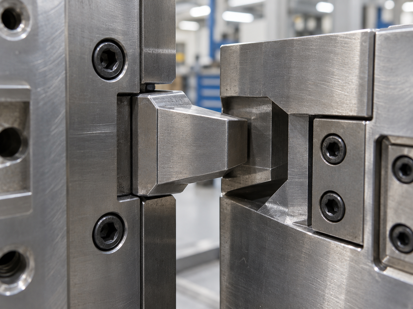
Injection mold interlock design is an important part of mold alignment, especially when the mold has large shut-off areas, deep cavities, sliders, or precision parting surfaces.
Guide pins and bushings can position the mold during opening and closing. However, they are not always enough to resist side pressure during injection. If the core and cavity shift slightly under pressure, the molded part may show flash, mismatch, uneven wall thickness, or dimensional variation.
A well-designed interlock helps the mold maintain accurate alignment throughout production.
What Is an Injection Mold Interlock?
An interlock is a precision-machined feature that helps the core side and cavity side locate against each other when the mold closes.
Common interlock designs include:
- Taper interlocks
- Side locks
- Rectangular locking blocks
- Conical interlocks
- Precision parting-line locks
- Integrated steel shut-off interlocks
Unlike standard guide pins, interlocks provide additional support close to the molding area.
This is especially useful when injection pressure creates lateral force on the cavity or core.
Why Injection Mold Interlock Design Matters
Good injection mold interlock design helps control several common mold problems.
| Problem | Possible Result |
|---|---|
| Core and cavity movement | Parting line mismatch |
| Side pressure during filling | Flash |
| Poor mold alignment | Uneven wall thickness |
| Repeated mold movement | Wear on shut-off surfaces |
| Large cavity offset | Dimensional instability |
| Slider or insert movement | Local mismatch or damage |
A mold may close correctly during trial, but small movement can still happen during actual injection.
This is why mold alignment should not depend only on guide pins.
For precision tooling, the interlock should work together with the injection mold design and the overall mold structure.
Guide Pins Are Not Enough for Every Mold
Guide pins mainly guide the mold during opening and closing.
They are necessary, but they have clearance. This clearance allows the mold to move smoothly without jamming.
However, that same clearance means guide pins cannot always prevent small side movement under high injection pressure.
This becomes more noticeable when the mold has:
- Deep box-shaped parts
- Large vertical shut-off surfaces
- Offset cavities
- Large sliders
- Automotive plastic parts
- Thin ribs close to the parting line
- High injection pressure
- Long cores
For these molds, interlocks provide additional positioning near the critical molding area.
Injection Mold Interlock Design for Side Pressure
Side pressure is one of the main reasons to add interlocks.
Imagine a deep cavity where most of the plastic pressure pushes toward one side of the core.
Even if the movement is only 0.02–0.05 mm, it may create:
- Visible mismatch
- Flash
- Uneven dimensions
- Extra polishing or fitting work
- Faster mold wear
The interlock should be positioned where it can resist this force directly.
Simply adding more guide pins far away from the cavity may not solve the real problem.
At Fentor Mold, we normally review the cavity layout, shut-off direction, slider position, and likely injection force before deciding where additional locking support is needed.
Where Should Interlocks Be Located?
There is no single position that works for every mold.
The location depends on the mold structure.
Near Large Shut-Off Areas
Large shut-off surfaces can generate strong side force.
Interlocks placed close to these areas help prevent relative movement between the two mold halves.
Around Large Cavities
For large plastic parts, cavity pressure can create uneven loading.
Interlocks can improve alignment around the cavity instead of relying only on four corner guide pins.
Near Sliders
Large sliders may create additional side load when the mold closes.
A suitable interlock can help stabilize the surrounding mold structure.
On Precision Parting Lines
For products with strict parting-line requirements, local interlocks help control mismatch.
This is especially important for visible surfaces or mating components.
Taper Interlocks vs. Straight Interlocks
Taper interlocks are commonly used because they can center the mold gradually during closing.
As the mold approaches the final closed position, the taper surfaces guide both halves into alignment.
Advantages include:
- Easier mold closing
- Good self-centering
- Reduced risk of direct collision
- Easier adjustment during fitting
However, the taper angle must be reasonable.
If the taper is too steep, the positioning effect becomes weaker. If it is too small, the interlock may lock too tightly or become difficult to release.
Straight or rectangular locks can provide strong positioning, but they require very accurate machining and fitting.
For many production molds, a combination of guide pins and tapered interlocks provides a practical balance.
Clearance Is Critical in Injection Mold Interlock Design
An interlock should not be designed too tight.
This is a common mistake.
If the fitting is excessively tight, several problems can happen:
- Mold closing becomes difficult
- Interlock surfaces gall
- Steel wears quickly
- Mold temperature changes affect fitting
- Locking blocks may crack
- Mold opening becomes unstable
On the other hand, too much clearance reduces the alignment function.
The correct fitting depends on:
- Mold size
- Steel material
- Mold temperature
- Interlock type
- Machining accuracy
- Expected side load
The goal is controlled contact, not excessive interference.
Interlock Steel and Hardness
Interlocks repeatedly contact each other during every mold cycle.
Therefore, wear resistance is important.
Common approaches include:
- Hardened tool steel
- Replaceable hardened locking blocks
- Surface-treated steel
- Standard precision mold components
Using softer untreated steel for a high-cycle interlock can cause the positioning accuracy to decrease over time.
Once the interlock wears, the mold may gradually develop flash or mismatch even if the first samples were acceptable.
This is one reason mold performance should be evaluated not only during the first trial but also after repeated cycling.
You can also read our article about injection mold wear for related mold maintenance considerations.
Machining Accuracy Matters More Than the Drawing
A good interlock design can still fail if machining accuracy is poor.
The important surfaces should be machined and inspected carefully.
Typical processes may include:
- CNC milling
- Grinding
- EDM
- Wire cutting
- Precision fitting
- Final spotting
The position of the interlock relative to the cavity is especially important.
If the locking block itself is accurate but its position is wrong, it may force the mold into the wrong alignment.
Fentor Mold uses CNC, EDM, wire cutting, grinding, and fitting processes to control these critical tooling areas during mold manufacturing.
Avoid Using Interlocks to Correct a Bad Mold Structure
Interlocks are not a solution for every alignment problem.
If the mold base is too weak, the cavity plate is too thin, or the slider support is insufficient, adding interlocks alone may not solve the issue.
The mold designer should also check:
- Mold plate thickness
- Support pillars
- Cavity and core insert size
- Slider locking angle
- Shut-off area
- Injection pressure
- Clamp force
- Cavity balance
Good injection mold interlock design should support the mold structure, not compensate for a weak design.
Interlocks and Parting Line Quality
Parting-line mismatch is especially visible on cosmetic plastic parts.
Even a small step may become obvious after painting, plating, texture, or assembly.
Interlocks help keep both mold halves aligned at the final closed position.
However, the parting surface itself must also be properly fitted.
A good mold should combine:
- Accurate mold base alignment
- Proper guide components
- Correct interlock design
- Good parting-surface fitting
- Stable mold structure
For complex shut-off areas, you may also refer to our guide on injection mold shut-off design.
Common Injection Mold Interlock Design Mistakes
Several mistakes appear repeatedly in mold projects.
Interlocks Are Too Far From the Cavity
The mold may still move locally even when the outer mold base looks stable.
The Locking Area Is Too Small
A small interlock may not resist the actual side force.
The Interlock Is Too Tight
This increases wear and can damage the locking surfaces.
Insufficient Hardness
Soft interlock surfaces lose accuracy after repeated cycles.
Poor Cooling Consideration
Temperature differences can change the fitting condition of large mold components.
Using Only Guide Pins
For molds with strong lateral forces, guide pins alone may not provide enough support.
How to Check Interlocks During Mold Trial
During mold trial, engineers should not only check whether the mold opens and closes smoothly.
They should also inspect:
- Parting-line mismatch
- Flash location
- Interlock contact marks
- Abnormal wear
- Uneven shut-off contact
- Slider movement
- Mold closing condition
If flash repeatedly appears on only one side of a cavity, mold alignment should be checked before simply welding the parting surface.
Sometimes the real problem is mold movement rather than insufficient steel.
Final Thoughts
Injection mold interlock design is a small part of the overall mold structure, but it can have a major effect on production stability.
The purpose of an interlock is not simply to make the mold tighter. It is to control core and cavity alignment where injection pressure and mold structure create a risk of movement.
For precision molds, large cavities, deep shut-offs, or molds with strong side forces, good interlock positioning, proper hardness, accurate machining, and correct fitting can reduce flash, mismatch, and long-term wear.
At Fentor Mold, we review these details together with the cavity structure, sliders, shut-offs, and mold strength before machining begins. This helps reduce alignment problems during trial and later production.