
Introduction
Injection molding simulation predicts filling, pressure, temperature, cooling, and potential defects before T1. A good simulation does not guarantee the same T1 result.The difference usually comes from different simulation and molding conditions. Material data, machine response, temperature, cooling, gates, and process settings can change the actual flow pattern. The key question is which variable caused T1 to differ from the simulation.
Why Does Injection Molding Simulation Predict Good Filling but T1 Still Fails?
The software calculates how the melt should move through the cavity under those conditions. During T1, the machine, material, mold, and thermal conditions may differ from these inputs.
How Does Injection Pressure Change the Simulation-to-T1 Result?
Injection pressure is one of the most important variables when comparing predicted filling with real molding. The simulation calculates pressure from injection speed, melt temperature, viscosity, gate design, and flow length. If the actual machine cannot maintain the same pressure profile, the melt may slow down before reaching the end of the cavity.
Even a small pressure difference can increase filling time and allow the melt front to cool before the cavity is completely filled.
Compare the simulated pressure with the actual machine pressure curve. If the difference is large, changing the steel should not be the first action. First, check injection speed, pressure limit, screw response, and gate restriction.
Why Does Melt Temperature Cause a Different Flow Pattern?
Melt temperature changes viscosity, and viscosity directly controls how easily plastic moves through the cavity. A simulation normally uses a defined melt temperature, but the actual polymer temperature may be different because of barrel settings, residence time, screw shear, material drying, or machine-to-machine variation.
When the actual melt is colder than the simulation input, flow resistance increases. Higher viscosity increases flow resistance and requires more pressure to reach the same location.
It can also change weld-line strength, surface appearance, packing behavior, and local shrinkage. When T1 does not match the simulation, measure the actual melt temperature and compare it with the simulation input. Do not judge the process by the machine setpoint alone.
Why Do Cooling and Material Behavior Create Different T1 Results?
This happens because the final part geometry is controlled not only by how the cavity fills, but also by how the polymer cools, shrinks, and develops internal stress.
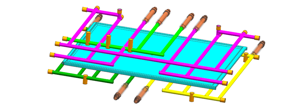
Cooling-channel layout, mold temperature, local wall thickness, and material shrinkage can therefore produce dimensional changes that were not obvious during the filling stage.
[
How Does Mold Temperature Affect Real Molded Parts?
Mold temperature controls how quickly the melt loses heat after entering the cavity. If the actual mold temperature is lower than the simulation condition, the polymer can freeze earlier near the cavity wall. This changes the effective flow area and can increase pressure requirements during filling.
A small temperature difference can change the position where the flow front freezes or where two flow fronts meet. This can produce a different weld-line location or a visible surface difference compared with the simulation.
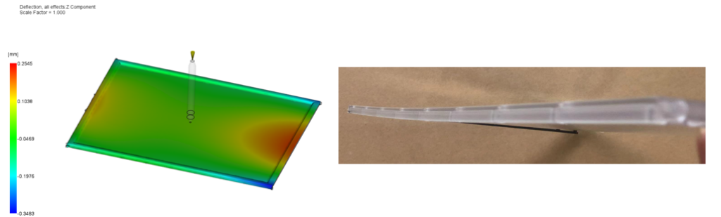
Mold temperature also affects shrinkage and dimensional stability. If one area of the cavity cools faster than another, the resulting shrinkage can become uneven. Therefore, when the simulated part looks dimensionally stable but T1 shows deformation, the engineer should compare actual mold temperatures and cooling performance instead of changing injection pressure alone.
Why Does Cooling Imbalance Cause Warpage After T1?
The root cause can be thermal imbalance. When different areas of a molded part cool at different rates, they develop different shrinkage levels. This creates internal stress, and the part may deform after ejection.
The real mold can behave differently. Channel distance, baffle efficiency, water flow, blocked passages, and local steel thickness can all change heat transfer.
The impact becomes clear during T1 when a large flat component looks correct immediately after ejection but bends after several hours. This is not necessarily evidence that the simulation failed. It indicates that the real thermal conditions were different from the assumed conditions.
What Should Engineers Compare When Simulation and T1 Results Do Not Match?
When simulation and real molded parts disagree, the most effective method is to compare variables in a fixed engineering sequence.
Compare the results in this order: filling behavior, pressure, temperature, cooling, and part dimensions.
If the root cause is process-related, steel modification may add cost without solving the problem. If the problem comes from the gate, runner, venting, cooling, or part geometry, simulation and T1 data can support a targeted mold modification.
How Does Flow Behavior Reveal a Filling Problem?
Engineers should compare the predicted flow-front sequence with the real filling sequence, especially at thin walls, ribs, corners, and end-of-fill areas.
For example, if the simulation predicts balanced filling but T1 shows one side filling much earlier, the cause may be runner imbalance, gate restriction, temperature difference, or actual material viscosity. The result can include weld-line movement, trapped air, hesitation, or short shot.
If the pressure is already close to the predicted requirement, the engineer should investigate gate restriction, melt temperature, venting, and flow resistance.
Why Can Mold Component Accuracy Affect the Final Result?
Simulation assumes that the mold geometry matches the designed model. Machining, EDM, grinding, assembly, or insert alignment can create small dimensional differences. These differences can change local clearances, gate dimensions, vent depth, or cavity geometry.
A slightly undersized gate can increase flow resistance. A mismatch at an insert can create flash. A dimensional difference in a cooling feature can also change heat transfer.
Precision CNC machining and mold component inspection can verify whether critical mold dimensions remain close enough to the simulation model to make a meaningful comparison.
The engineering conclusion is that injection molding simulation should be treated as a controlled prediction, not a guarantee of the T1 result. Simulation becomes valuable when its assumptions are checked against actual machine pressure, melt temperature, mold temperature, flow behavior, cooling performance, and part dimensions. When these variables are matched, simulation can reduce unnecessary mold rework and make T1 troubleshooting much faster.