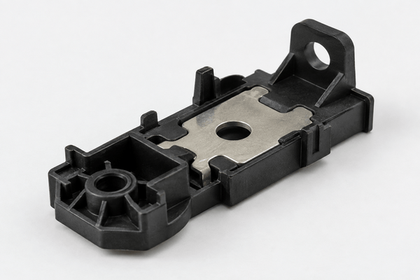
A metal injection mold works under harder conditions than many standard plastic injection molds. The feedstock contains fine metal powder mixed with a binder. During injection, these particles can cause strong abrasive wear on the gate, runner, cavity, core, and ejector system.
If the mold is not designed for this wear, gate dimensions may change, flash may increase, and part dimensions may slowly drift.
For this reason, improving metal injection mold life requires more than choosing a harder steel. Tool steel, gate design, surface treatment, ejection, cooling, and preventive maintenance must all work together.
Why Does a Metal Injection Mold Wear Faster?
Metal injection molding, also called MIM, uses feedstock made from metal powder and polymer binder.
The metal particles make the material much more abrasive than ordinary unfilled plastics.
As the feedstock moves through the mold, high-speed flow can gradually wear:
- Gates
- Runner corners
- Cavity surfaces
- Core pins
- Slides
- Lifters
- Ejector pin holes
The highest wear usually appears where the melt changes direction or passes through a small section.
Gate areas are especially important because the feedstock reaches high speed there.
MIM tooling must therefore resist abrasion, erosion, galling, and repeated mechanical movement.
Choose the Right Steel for a Metal Injection Mold
Tool steel selection has a major effect on mold life.
A low-cost steel may be acceptable for prototype production. However, it may wear too quickly in long production runs.
Common options include:
| Mold Steel | Wear Resistance | Typical Use |
|---|---|---|
| P20 | Low to medium | Prototype or low-volume tooling |
| H13 | Medium | General MIM cavities and cores |
| D2 | High | Gates and high-wear inserts |
| S7 | High | Core pins, slides and impact areas |
| Powder metallurgy steel | Very high | High-volume abrasive applications |
| Carbide inserts | Extremely high | Critical gate or wear areas |
H13 is often used because it offers a good balance between toughness, heat resistance, and machinability.
However, high-wear areas may need D2, S7, powder metallurgy steel, or carbide inserts.
Recent MIM tooling guidance also emphasizes that abrasive metal feedstocks can require significantly harder tooling than standard plastic molds.
Metal Injection Mold Gate Design Has a Major Effect on Tool Life
The gate is often one of the first areas to wear.
A gate that is too small can create very high flow velocity.
This increases erosion around the gate and nearby cavity surface.
In addition, excessive shear may separate the powder and binder.
A gate that is too large can also create processing problems.
Therefore, gate size must balance:
- Filling pressure
- Flow speed
- Shear rate
- Gate mark requirements
- Part geometry
- Feedstock viscosity
Gate location is also important.
The feedstock should enter the cavity without directly hitting a thin steel feature or sharp core.
Otherwise, the metal powder can repeatedly attack the same area.
Over thousands of cycles, this may create serious wear.
MIM tooling references specifically note that very small gates can increase flow speed and accelerate tool wear.
Use Replaceable Inserts in High-Wear Areas
Not every mold area needs the most expensive steel.
A more practical approach is to use replaceable inserts.
Typical insert locations include:
- Gate areas
- Small core features
- Thin ribs
- Shut-off areas
- High-flow zones
- Critical dimensions
If one area wears first, the insert can be replaced without rebuilding the complete mold.
This reduces maintenance cost.
It also makes dimensional correction easier.
For long-running projects, replaceable gate and cavity inserts can greatly improve the usable life of a metal injection mold.
They are especially useful when the part has very tight tolerances.
Improve Surface Hardness With Coatings
Surface coatings can provide additional wear protection.
Common coatings include:
- TiN
- CrN
- DLC
- Other PVD coatings
The correct coating depends on the feedstock, steel, mold temperature, and required surface finish.
A coating should not be used to hide poor base steel or poor heat treatment.
Instead, it should support a properly hardened mold.
High-wear MIM molds may benefit from PVD coatings because they reduce surface friction and protect critical areas from abrasive wear.
Avoid Sharp Corners in Metal Injection Mold Design
Sharp internal mold details are difficult for several reasons.
First, they create stress concentration in the tool.
Second, metal powder flow may attack the corner directly.
Third, small sharp features are easier to damage during production or maintenance.
Whenever the product design allows it, use suitable radii.
For example:
- Add radii around internal corners
- Avoid very thin unsupported steel
- Strengthen narrow core sections
- Reduce unnecessary sharp transitions
This improves both mold strength and feedstock flow.
MIM design guidance commonly recommends internal radii because sharp corners increase stress and can contribute to tool wear.
Control Injection Speed Near High-Wear Areas
Higher injection speed may help fill thin sections.
However, higher speed also increases the energy of the metal powder hitting the mold surface.
This can accelerate erosion.
Therefore, the fastest possible filling speed is not always the best setting.
Instead, engineers should check:
- Flow-front stability
- Injection pressure
- Gate velocity
- Shear rate
- Surface defects
- Powder-binder separation
A staged injection profile may sometimes reduce impact on the gate and cavity.
The goal is stable filling with enough speed, but without unnecessary erosion.
Metal Injection Mold Venting Must Stay Clean
Good venting does more than prevent burn marks.
It also helps reduce excessive cavity pressure.
If air cannot escape, injection pressure may rise.
Higher pressure creates more load on:
- Parting lines