
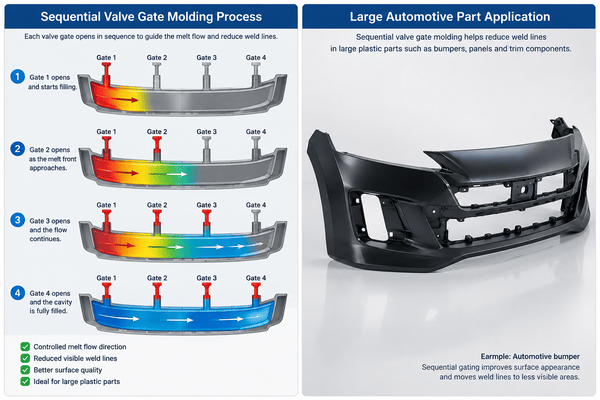
Large plastic parts often need several gates. One gate may not provide enough flow length or pressure.
However, multiple gates can create another problem: weld lines.
When two melt fronts meet, a visible line may appear on the part surface. In some cases, this area can also become weaker.
Sequential valve gate molding helps control this problem. It opens each valve gate in a planned order. This allows the melt to flow in one main direction instead of forming several uncontrolled flow fronts.
This method is widely used for automotive parts, appliance housings, large panels, and other molded parts with demanding surface requirements.
What Is Sequential Valve Gate Molding?
Sequential valve gate molding uses a hot runner system with several valve gates.
Each gate can open and close independently.
Instead of opening every gate at the same time, the system opens them one after another.
For example:
- Gate 1 opens and starts filling the cavity.
- The melt front moves toward Gate 2.
- Gate 2 opens before or when the melt reaches that area.
- The flow continues toward the next gate.
- The remaining gates open in sequence.
This creates a smoother filling direction.
As a result, the process can reduce visible weld lines and improve part appearance.
Why Weld Lines Form in Large Parts
Large parts often need multiple gates because the flow distance is long.
If all gates open together, several melt fronts move through the cavity at the same time.
Eventually, they meet.
This meeting area becomes a weld line.
Several conditions can make the line more visible:
- Low melt temperature
- Low mold temperature
- Long flow distance
- Slow injection speed
- Poor venting
- Incorrect gate position
- Uneven wall thickness
- Glass-fiber-reinforced materials
- Early cooling of the melt front
For some parts, the weld line is only a cosmetic problem.
For other parts, it may also reduce local strength.
Therefore, flow direction must be controlled carefully.
How Sequential Valve Gate Molding Reduces Weld Lines
The main benefit of sequential valve gate molding is better flow control.
With normal multi-gate filling, two melt fronts may move toward each other.
When they meet, a weld line forms.
Sequential valve gate molding works differently.
The first gate creates the main melt flow. Then, the next gate opens as the melt front approaches that area.
Fresh melt from the new gate joins the existing flow.
This reduces direct melt-front collision.
As a result, the weld line may become weaker, less visible, or move to a better location.
| Filling Method | Flow Behavior | Weld Line Risk |
|---|---|---|
| Single gate | One main melt front | Low, but flow may be too long |
| Multiple gates open together | Several melt fronts meet | High |
| Sequential valve gates | Flow moves in a controlled direction | Lower |
| Poor valve timing | Unstable filling | Medium to high |
Sequential Valve Gate Molding Needs Correct Timing
Valve gate timing is very important.
If the next gate opens too early, two melt fronts may still collide.
Therefore, the weld line may remain visible.
If the gate opens too late, the existing melt front may cool too much.
This can create:
- Flow marks
- Hesitation marks
- Gloss differences
- Pressure changes
- Transition lines
- Short shots
For this reason, engineers should not rely only on a fixed time delay.
The correct opening point depends on the actual melt-front position.
Moldflow analysis can help engineers predict this position before the mold is built.
At Fentor Mold, we review gate positions, filling direction, wall thickness, and hot runner layout during the early tooling stage. Our injection mold manufacturing service includes DFM review and tooling evaluation before machining starts.
Gate Position Also Affects Weld Lines
Good timing cannot fix a poor gate layout.
Gate position must support the natural flow direction of the part.
For example, a long automotive panel may need several gates along the main flow path.
The first gate starts the filling process.
Then, the following gates open as the melt front moves across the cavity.
This helps create a smoother flow pattern.
However, poor gate locations can still create opposite melt fronts.
Engineers should check:
- Part geometry
- Wall thickness
- Rib locations
- Cosmetic areas
- Flow length
- Gate marks
- Injection pressure
- Clamp force
- Hot runner layout
Good gate design and good timing must work together.
Sequential Valve Gate Molding for Large Automotive Parts
Large automotive parts are common applications for this technology.
Typical examples include:
- Bumper parts
- Door panels
- Instrument panel parts
- Large trim panels
- Grilles
- Exterior panels
- Structural housings
These parts often have long flow paths.
At the same time, many surfaces are visible after assembly.
Therefore, weld lines and flow marks may not be acceptable.
Sequential valve gate molding can move the weld line away from important areas.
For example, engineers may move it toward:
- A hidden edge
- A rib
- A hole
- A non-cosmetic area
- The back side of the part
In some cases, the weld line cannot be removed completely.
However, it can often be moved to a better position.
Moldflow Helps Optimize Sequential Valve Gate Molding
Moldflow analysis is useful because it predicts how the melt moves through the cavity.
It can show:
- Flow-front position
- Filling time
- Injection pressure
- Weld-line location
- Air traps
- Temperature changes
- Shear rate
- Clamp force
Engineers can then test different valve gate sequences.
For example, Gate 2 may open when the melt front is close to the gate.
Gate 3 may need a different delay because the wall thickness is different.
Therefore, using the same delay for every valve gate is not always the best solution.
Moldflow helps reduce trial-and-error during mold testing.
Melt and Mold Temperature Still Matter
Sequential valve gate molding improves the flow pattern.
However, process settings are still important.
If the melt is too cold, the flow front loses heat quickly.
The fresh melt from the next gate may not join smoothly.
A low mold temperature can create the same problem.
Engineers may need to adjust:
- Melt temperature
- Mold temperature
- Injection speed
- Holding pressure
- Valve timing
- Screw position
- Hot runner temperature
However, temperatures should stay within the material supplier’s recommended range.
Excessive temperature can cause other defects.
These may include material degradation, burning, color change, or longer cycle times.
Venting Must Match the Filling Direction
Air must leave the cavity as plastic enters.
Sequential valve gate molding changes the filling direction.
Therefore, it can also change where air becomes trapped.
Poor venting may cause:
- Burn marks
- Short shots
- Surface defects
- Weak weld areas
- Unstable filling
Vents should be placed near the final filling areas.
Common venting positions include:
- Parting lines
- Insert areas
- Ejector locations
- Deep ribs
- End-of-flow areas
Good venting helps reduce pressure and improves filling stability.
Common Sequential Valve Gate Molding Problems
Incorrect settings can create new defects.
| Problem | Possible Cause | Typical Adjustment |
|---|---|---|
| Visible weld line | Next gate opens too early | Delay gate opening |
| Flow mark near gate | Gate opens too late | Open gate earlier |
| Gloss difference | Uneven flow or temperature | Adjust timing and temperature |
| Pressure fluctuation | Poor gate sequence | Change opening order |
| Short shot | Excessive delay | Open next gate earlier |
| Burn mark | Trapped air | Improve venting |
| Gate mark | Valve pin or gate issue | Check hot runner design |
During mold trials, it is better to change one main parameter at a time.
This makes the result easier to judge.
Sequential Valve Gate Molding vs Standard Hot Runner Molding
A standard hot runner system can also use several gates.
However, all gates may open at the same time.
This can create several melt fronts.
As a result, weld lines may become more visible.
Sequential valve gate molding gives engineers more control.
It can control both flow direction and gate timing.
This method is especially useful when:
- The part is large
- The surface is visible
- The flow distance is long
- Several gates are needed
- Weld lines must be controlled
- Filling balance is difficult
The system is more complex than a simple hot runner mold.
Tooling cost may also be higher.
However, for large cosmetic parts, the improvement in part quality can justify the added cost.
Reduce Trial-and-Error During Mold Testing
Some valve gate systems are adjusted only after the first mold trial.
This can work, but it may require many tests.
A better method is to combine:
- DFM review
- Moldflow analysis
- Gate layout planning
- Hot runner design
- Valve timing optimization
- Controlled mold trials
This approach can reduce later mold changes.
It also helps shorten the development process.
For demanding plastic parts, Fentor Mold can support both tooling and injection molding production. This allows the mold design and process settings to be checked during actual production trials.
Final Thoughts
Sequential valve gate molding is an effective way to reduce weld lines in large plastic parts.
However, the result depends on more than the valve gates themselves.
Gate location, opening sequence, mold temperature, melt temperature, venting, and hot runner design all affect the final part.
When these factors work together, the melt can move through the cavity in a smoother direction.
As a result, manufacturers can reduce visible weld lines, improve surface quality, and create a more stable injection molding process.