
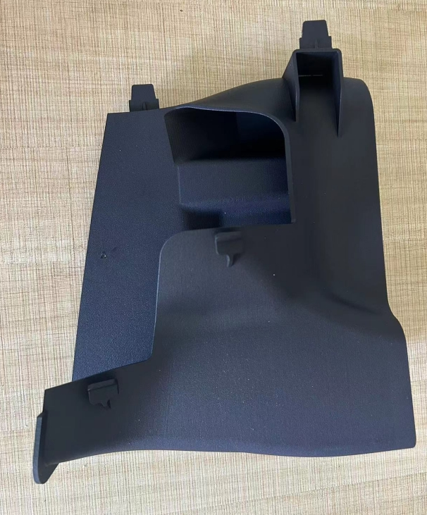
PA12 injection molding offers good dimensional stability, chemical resistance, low moisture absorption, and strong impact performance. Because of these properties, PA12 is widely used for automotive components, fluid connectors, electrical parts, industrial housings, clips, and other precision plastic products.
However, shrinkage and warpage can still become serious problems, especially on large, flat, thin-wall, or dimensionally critical parts. A component may look acceptable after molding but fail dimensional inspection several hours later.
To control these problems, manufacturers need to consider the part design, mold structure, gate position, cooling system, and molding process together.
At Fentor Mold, we normally review these risks during DFM and mold design instead of relying only on process adjustments after the mold is completed.
What Causes Shrinkage in PA12 Injection Molding?
PA12 is a semi-crystalline thermoplastic. During cooling, its molecular structure changes as the material solidifies. Therefore, some molding shrinkage is unavoidable.
The real engineering goal is not to eliminate shrinkage. Instead, the goal is to make it predictable, uniform, and repeatable.
Several factors can affect PA12 shrinkage:
| Factor | Possible Effect |
|---|---|
| Wall thickness | Thick areas may shrink more |
| Mold temperature | Changes crystallization and cooling behavior |
| Packing pressure | Insufficient packing increases shrinkage |
| Packing time | Short packing may cause dimensional variation |
| Gate size | Early gate freeze limits packing |
| Gate location | Creates different flow and shrinkage directions |
| Cooling | Uneven cooling increases distortion |
| Part geometry | Ribs and thick sections create local shrinkage |
Because these factors interact, changing only one machine setting may not solve the problem.
Why Does PA12 Warpage Occur?
Warpage happens when different areas of a molded part shrink by different amounts.
For example, one side may cool faster than the other. One section may also receive more packing pressure because it is closer to the gate.
As a result, internal stress becomes unbalanced. Once the part leaves the mold, that stress can pull the component out of shape.
Typical PA12 warpage appears as:
- Bowing of flat surfaces
- Twisting of long parts
- Uneven edges
- Hole-position changes
- Distorted assembly features
- Poor flatness
- Misaligned sealing surfaces
Therefore, controlling PA12 injection molding warpage starts with reducing uneven shrinkage.
PA12 Injection Molding Starts With Material Control
Although PA12 generally absorbs less moisture than PA6 and PA66, material condition still matters.
Excessive moisture can affect processing stability and final part quality. Therefore, resin storage and drying should follow the material supplier’s recommendations.
Do not assume that every PA12 grade requires exactly the same drying conditions. Reinforced PA12, flame-retardant grades, and other modified materials may have different requirements.
In addition, regrind percentage should remain controlled. Large changes in material condition can introduce another variable when engineers are trying to stabilize dimensions.
For precision parts, consistent material preparation is the first step toward consistent molding.
Keep Wall Thickness Uniform
Uneven wall thickness is one of the most common design causes of shrinkage variation.
Consider a housing with a 2 mm main wall and a local 5 mm section. The thick area cools more slowly and contains more material. Consequently, it may shrink differently from the surrounding wall.
This can create:
- Sink marks
- Local deformation
- Dimensional changes
- Internal stress
Whenever possible, keep the main wall thickness uniform.
If additional strength is required, ribs are usually better than making a large area significantly thicker.
However, rib thickness also needs control. Very thick ribs can create sink marks and local shrinkage on the opposite surface.
Early DFM analysis during custom injection mold manufacturing can identify these risks before mold steel is cut.
Gate Position Affects PA12 Shrinkage and Warpage
Gate position is one of the most important mold-design decisions for dimensional stability.
A poorly positioned gate can produce an unbalanced filling pattern. It may also create large differences in packing pressure across the cavity.
For example, material close to the gate may receive strong packing pressure, while an area far from the gate receives much less.
This difference can cause uneven shrinkage.
When choosing the gate position, engineers should consider:
| Gate Consideration | Why It Matters |
|---|---|
| Flow length | Affects pressure loss |
| Wall thickness | Influences filling direction |
| Critical dimensions | Packing can affect final size |
| Weld lines | Gate position controls their location |
| Flatness | Uneven flow may increase distortion |
| Appearance | Gate marks may need to be hidden |
| Venting | Air needs a clear escape path |
For complex PA12 parts, Moldflow analysis can help predict filling and packing behavior before tooling.
Use the Right Gate Size
Gate size matters as much as gate position.
If the gate freezes too early, packing pressure can no longer enter the cavity. The part then continues cooling without enough compensation for material shrinkage.
This may cause excessive shrinkage or dimensional variation.
On the other hand, simply making every gate very large is not the answer. Gate size also affects gate marks, cycle time, trimming, and part appearance.
The gate should therefore remain open long enough to provide effective packing while still meeting the product requirements.
Control Mold Temperature Consistently
Mold temperature influences the cooling rate and crystallization behavior of PA12.
More importantly, temperature balance across the mold affects warpage.
Imagine that one side of a part runs hotter than the other. The two sides will not cool and shrink under the same conditions.
Even when the average mold temperature looks correct, the finished part may still bend.
Therefore, engineers should check more than the temperature displayed on the temperature controller.
They should also consider:
- Cooling channel location
- Cooling channel diameter
- Distance from the cavity
- Water-flow rate
- Inlet and outlet temperature
- Hot spots around cores
- Cooling around deep ribs and bosses
A well-designed cooling system is especially important for flat and dimensionally sensitive PA12 parts.
Improve PA12 Injection Molding With Balanced Cooling
Cooling should follow the geometry of the plastic part as closely as practical.
Large differences in steel thickness can create different heat-transfer conditions. Deep cores may also remain hotter than the cavity side.
As a result, the inside and outside surfaces of a molded component can shrink differently.
For difficult areas, the mold may require additional cooling methods such as:
- Baffles
- Bubblers
- Separate cooling circuits
- Cooling inserts
- High-conductivity inserts where appropriate
However, the objective is not simply to make the mold colder.
The objective is to achieve uniform and controlled heat removal.
This is an important part of stable injection molding production, especially when dimensional consistency matters across long production runs.
Optimize Packing Pressure and Packing Time
Packing is another major factor affecting PA12 shrinkage.
After the cavity fills, additional material enters the cavity during the packing stage to compensate for volumetric shrinkage.
If packing pressure is too low, the part may show:
- Higher shrinkage
- Sink marks
- Dimensional instability
However, excessive packing is also undesirable. It can increase residual stress, create flash, or make ejection more difficult.
Packing time also needs to match the gate freeze time.
Once the gate freezes, extending the packing time provides little additional benefit.
Therefore, a stable process should identify the effective packing window rather than simply using the highest possible pressure or longest possible time.
Check Injection Speed and Filling Balance
Injection speed can influence the filling pattern and pressure distribution.
If the melt fills different sections at very different speeds, the final shrinkage may also become less uniform.
For multi-cavity molds, filling balance becomes even more important.
One cavity should not consistently fill and pack earlier than another. Otherwise, part dimensions may vary between cavities even when all parts come from the same molding cycle.
Therefore, during mold trials, compare:
- Cavity filling
- Part weight
- Critical dimensions
- Gate freeze behavior
- Warpage
- Surface quality
Do not judge mold performance only by whether every cavity produces a complete part.
Ribs and Bosses Can Create Local Warpage
Ribs and bosses are necessary on many engineering components, but they also change local material thickness and stiffness.
A dense rib structure on only one side of a flat surface can create an unbalanced part design.
Similarly, a large boss may cool much more slowly than the surrounding wall.
These features can pull the part as it shrinks.
Therefore, DFM should review:
- Rib thickness
- Rib spacing
- Boss thickness
- Connection between bosses and walls
- Local material accumulation
- Draft angles
- Flow direction around these features
Small geometry changes before tooling can sometimes prevent much larger mold modifications later.
Consider Reinforced PA12 Separately
Not all PA12 materials behave in the same way.
Glass-fiber-reinforced PA12, for example, can show stronger directional shrinkage because fiber orientation follows the material flow.
This means shrinkage in the flow direction may differ from shrinkage across the flow direction.
Consequently, gate location becomes even more important.
For reinforced PA12 components, engineers should evaluate fiber orientation together with:
- Flow direction
- Part geometry
- Gate position
- Flatness requirements
- Critical dimensions
Using a generic shrinkage percentage without considering material orientation can lead to incorrect mold dimensions.
Do Not Depend Only on the Material Shrinkage Rate
A material datasheet may provide a molding shrinkage range. However, that number should not automatically become the shrinkage value for every mold dimension.
Actual shrinkage depends on the specific:
material + geometry + flow direction + gate + mold temperature + packing + cooling condition.
For this reason, precision mold dimensions often require engineering judgment.
Critical dimensions can also be designed steel-safe where practical. After T0 or T1 samples are measured, engineers can adjust the mold based on actual molding results.
This approach is often safer than making aggressive corrections before real sample data is available.
Measure PA12 Parts at a Consistent Time
Another common mistake is measuring molded parts at inconsistent times.
A PA12 part may continue to change after ejection as it cools and reaches equilibrium.
If one sample is measured immediately and another is measured much later, the results may not be directly comparable.
Therefore, dimensional inspection should use a defined conditioning and measurement procedure.
For important dimensions, record:
| Inspection Item | Purpose |
|---|---|
| Measurement time | Keep results comparable |
| Part temperature | Reduce measurement variation |
| Cavity number | Identify cavity-to-cavity differences |
| Process condition | Connect dimensions to molding settings |
| Critical dimensions | Track functional performance |
| Flatness/warpage | Monitor deformation |
Consistent measurement makes mold adjustment decisions much more reliable.
Use Mold Trials to Find the Real Cause
When a PA12 part is warped, immediately changing the steel is risky.
First, determine whether the problem comes from the mold, product design, or molding process.
A structured mold trial can test changes in:
- Packing pressure
- Packing time
- Mold temperature
- Injection speed
- Cooling time
If the warpage changes significantly with processing conditions, the problem may not require immediate steel modification.
However, if the same deformation remains under a reasonable processing window, the gate, cooling system, or part geometry may need further review.
At Fentor Mold, we prefer to measure and compare trial results before deciding on mold modification. This helps avoid unnecessary steel changes.
PA12 Injection Molding Shrinkage and Warpage Checklist
Before approving a PA12 mold for production, check the following:
| Area | What to Check |
|---|---|
| Material | Correct PA12 grade and stable condition |
| Part design | Reasonably uniform wall thickness |
| Ribs/bosses | No excessive local thickness |
| Gate | Suitable location and size |
| Filling | Balanced flow pattern |
| Packing | Stable pressure and effective time |
| Cooling | Balanced cavity and core temperature |
| Mold temperature | Consistent during production |
| Dimensions | Critical features measured |
| Warpage | Flatness and deformation checked |
| Multi-cavity mold | Cavity-to-cavity consistency |
| Measurement | Consistent inspection conditions |
This checklist helps separate different sources of dimensional variation instead of treating every problem as a simple shrinkage issue.
Final Thoughts
Controlling shrinkage and warpage in PA12 injection molding requires more than changing a shrinkage percentage in the mold design.
Part geometry, gate position, packing, mold temperature, cooling balance, and material grade all affect the final dimensions. Reinforced PA12 materials can make the situation even more complex because fiber orientation introduces directional shrinkage.
Therefore, the best approach is to identify dimensional risks during DFM, design the mold for balanced filling and cooling, and then verify the results through controlled mold trials.
Fentor Mold provides mold design, mold manufacturing, trial molding, dimensional inspection, and plastic components manufacturing for custom plastic parts. By combining tooling and molding analysis, we can identify the real cause of shrinkage or warpage before making unnecessary mold modifications.