
What Are Flow Marks on PC Parts?
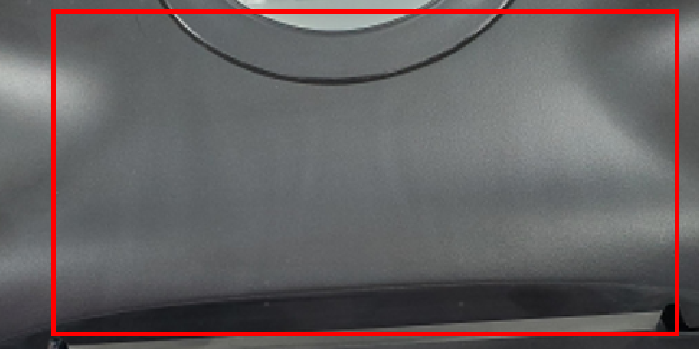
Flow marks are visible lines or patterns on the surface of an injection molded part.
They are especially noticeable on PC parts with smooth, glossy, or transparent surfaces.
Flow marks usually appear when the plastic flow becomes unstable during filling. The problem is often related to the gate, mold temperature, filling speed, or product design.
For difficult PC parts, it is better to solve the problem through mold design rather than simply adjusting the injection machine.
1. Check the Gate Design First
The gate is one of the most important factors.
If the gate is too small, the PC material must pass through a restricted area at high shear. This can create unstable flow and visible marks near the gate.
A suitable gate size allows the material to enter the cavity more smoothly.
Gate location also matters. The plastic should ideally flow through the part in a controlled direction.
Our injection mold manufacturing service includes gate and runner design based on the product structure.
2. Increase Mold Temperature
PC needs a relatively high mold temperature compared with common materials such as PP or ABS.
If the mold surface is too cold, the material can cool quickly as it touches the cavity wall.
The next material layer then flows over a partially cooled surface.
This can create visible flow lines.
A suitable mold temperature keeps the material flowing smoothly and gives the surface more time to replicate the cavity.
3. Control Filling Speed
Filling too slowly can allow the PC to cool before the cavity is completely filled.
Filling too quickly can increase shear and may create other surface defects.
The goal is not simply to use the highest injection speed.
The filling speed should match the gate size, wall thickness, flow length, and mold temperature.
For complex products, mold flow analysis can help identify areas where the flow changes suddenly.
4. Avoid Sudden Wall Thickness Changes
Large changes in wall thickness can disturb the plastic flow.
When PC moves from a thick section into a thin section, the flow front can change speed and direction.
This can leave visible marks on the surface.
A more uniform wall thickness usually gives better flow behavior.
If a thicker structure is required, ribs or other design features can often provide the required strength without creating a large solid section.
5. Improve Runner Design
A poor runner system can also cause unstable filling.
The runner should provide balanced and smooth material flow.
For multi-cavity molds, each cavity should receive material as evenly as possible.
For large PC parts, multiple gates may be necessary to reduce flow length and pressure.
Our prototype injection molding service can help verify the filling behavior before committing to a production mold.
6. Check Mold Venting
Poor venting can make filling more difficult.
Trapped air increases resistance at the end of the flow path. The machine may then require higher pressure to fill the cavity.
Proper vents allow air to escape and help maintain a stable flow front.
Venting is particularly important around the end of fill and areas where several flow fronts meet.
7. Use Mold Flow Analysis for Difficult PC Parts
For simple products, experience may be enough to select the gate and runner design.
For large or complex PC parts, mold flow analysis can save significant trial-and-error time.
It can help check:
- Filling pattern
- Flow front temperature
- Injection pressure
- Weld line locations
- Air traps
- Gate positions
The analysis gives the mold designer a better understanding of the filling process before machining begins.
How to Reduce Flow Marks
A practical approach is:
- Select a suitable gate location.
- Use an appropriate gate size.
- Keep the mold temperature stable.
- Optimize filling speed.
- Avoid sudden wall thickness changes.
- Balance the runner system.
- Improve mold venting.
- Use mold flow analysis for difficult parts.
Final Thoughts
Flow marks on PC injection molded parts are usually caused by unstable material flow and rapid cooling at the mold surface.
Increasing injection speed alone is not always the right solution.
Start with the gate, runner, mold temperature, product design, and venting.
A well-designed mold can reduce flow marks before the first molding trial and make the process much easier to control.
For more information about our capabilities, see our injection molding production service.
You can also find more practical injection molding topics on the Fentormold blog.