
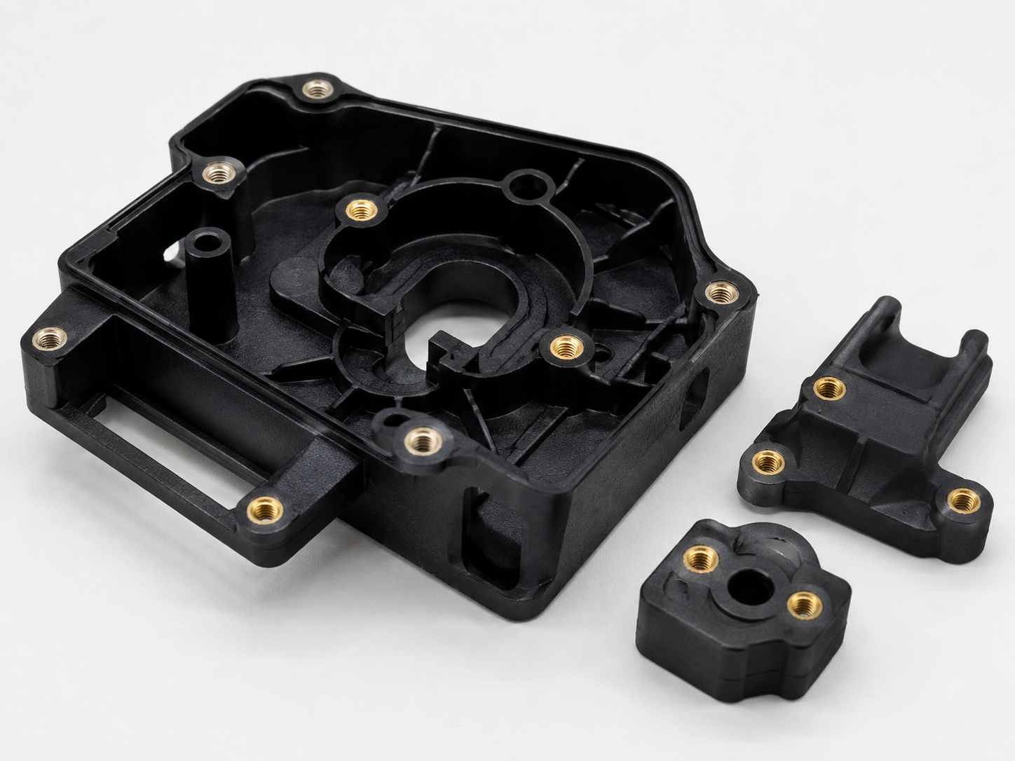
Plastic insert molding can combine metal inserts and molded plastic into one finished component, reducing later assembly and improving part strength.
But it also introduces risks that ordinary injection molding does not have.
The insert has to be placed in the correct position, held firmly during injection, sealed properly against the mold, and remain stable while molten plastic fills the cavity under pressure.
If any of these conditions are not controlled, the result may be:
- Insert movement
- Flash around the insert
- Poor plastic coverage
- Insert rotation
- Cracking
- Incorrect dimensions
- Missing inserts
- Inserts placed in the wrong direction
- Mold damage
- Unstable production
For buyers, the main challenge is not whether plastic insert molding can be done.
It is whether the mold and production process can repeat the same result over thousands of cycles.
Why Plastic Insert Molding Has More Production Risk
In normal injection molding, the mold mainly controls the plastic.
With insert molding, the mold also needs to control another component before the plastic enters the cavity.
That component may be:
- Threaded metal inserts
- Bushings
- Pins
- Terminals
- Electrical contacts
- Metal plates
- Magnets
- Shafts
- Small machined components
Each insert has its own size, tolerance, orientation, surface condition, and production variation.
The mold therefore needs to manage both the insert and the plastic at the same time.
That makes plastic insert molding more sensitive to tooling accuracy and process consistency.
Start With a Stable Insert Design
The insert itself should be designed with molding in mind.
A simple smooth cylindrical pin may be easy to manufacture, but it may not lock securely inside the molded plastic.
Depending on the application, the insert may need features such as:
- Knurling
- Grooves
- Undercuts
- Flats
- Holes
- Shoulders
- Steps
These features help the plastic mechanically lock around the insert.
Without enough mechanical retention, the insert may pull out or rotate during later assembly.
Threaded inserts are a common example.
If the insert is expected to resist tightening torque, the external geometry should prevent rotation inside the plastic.
The correct insert shape depends on the direction of load.
Pull-out resistance and torque resistance are not exactly the same design problem.
Plastic Insert Molding Requires Good Insert Positioning
The insert must sit in a repeatable position inside the mold.
A small position error can affect:
- Hole location
- Thread position
- Plastic wall thickness
- Assembly alignment
- Sealing
- Part appearance
The mold should therefore locate the insert using clear mechanical references.
Depending on the insert, these may include:
- Diameter location
- End-face location
- Shoulders
- Pins
- Pockets
- Magnetic holding
- Spring pressure
The important point is that the insert should not rely on the operator simply placing it “approximately” in the correct position.
The mold itself should define where the insert belongs.
For custom projects, our Injection Mold Manufacturing service covers mold design, machining, fitting, trial, and modification before repeat production.
Prevent Insert Rotation Before Injection
Round inserts can create another problem.
Even when the insert is located correctly, it may rotate.
This matters when the insert includes:
- A flat surface
- An offset hole
- An electrical terminal
- A slot
- A directional feature
- A specific thread orientation
The mold should include an anti-rotation feature where required.
This may use:
- Flat-to-flat location
- Keyways
- Slots
- Pins
- Shaped pockets
Trying to control orientation only through manual placement is risky during long production runs.
Operators may place hundreds or thousands of inserts per shift.
A design that physically prevents incorrect orientation is much safer.
Seal the Insert Correctly to Prevent Flash
Flash around the insert is one of the most common plastic insert molding problems.
The mold needs to shut off against the insert closely enough to stop molten plastic from leaking into unwanted areas.
But the insert itself also has manufacturing tolerance.
If the insert diameter varies, the shutoff condition changes.
If the mold is designed too tight:
- Inserts may not fit
- Loading becomes difficult
- Insert surfaces may be damaged
- Mold components may wear
If the shutoff is too loose:
- Flash can appear
- Threads can become contaminated
- Functional surfaces may need secondary cleaning
This is why the supplier needs the actual insert tolerance before finalizing the mold.
Do not design the shutoff around one perfect sample insert.
The tooling should consider the real production range.
Insert Tolerance Can Become a Mold Problem
Buyers sometimes focus only on the plastic part drawing and ignore the insert drawing.
That is risky.
Insert dimensions can directly affect mold performance.
Important dimensions may include:
- Outside diameter
- Length
- Shoulder thickness
- Flat width
- Hole location
- Thread dimensions
Suppose the mold uses the insert diameter for both location and sealing.
If the insert supplier later changes the diameter slightly, the molding process may suddenly develop flash or loading problems.
For plastic insert molding, the insert specification should therefore be treated as part of the tooling specification.
The final approved insert drawing and tolerance should be controlled just like the plastic part drawing.
Hold the Insert Against Injection Pressure
During molding, molten plastic enters the cavity at high pressure.
That pressure can push the insert away from its intended position.
This is especially likely when:
- The insert has a large exposed surface
- The gate is close to the insert
- The flow hits one side directly
- The insert is long or thin
- The insert is only lightly located
The mold should support the insert in the direction of the expected force.
Spring-loaded pins, fixed supports, magnets, or shaped pockets may be used depending on the design.
The correct method depends on the insert geometry and molding conditions.
This is an important reason to review gate location together with insert position.
If the melt flow directly impacts the insert, gate changes may reduce movement more effectively than simply increasing holding force.
Gate Position Matters in Plastic Insert Molding
Gate location affects more than filling.
It also affects how much force is applied to the insert during injection.
A gate positioned directly opposite a small metal insert may cause the melt to hit the insert before the cavity fills.
This can lead to:
- Insert movement
- Insert tilt
- Uneven plastic thickness
- Weld lines
- Local stress
A better gate location may allow the melt to flow around the insert more evenly.
This can improve both filling and insert stability.
Gate design should therefore consider:
- Insert location
- Flow direction
- Part wall thickness
- Weld-line location
- Cosmetic surfaces
- Critical dimensions
Our Injection Mold Design Guide explains how gate position, filling, venting, ejection, and mold structure need to be evaluated together.
Avoid Plastic That Is Too Thin Around the Insert
A metal insert often creates a local reduction in plastic wall thickness.
If the remaining plastic layer is too thin, the molded area may become weak.
Possible problems include:
- Cracking
- Poor filling
- Exposed metal
- Weak weld lines
- Stress concentration
The required plastic thickness depends on the material, part geometry, and load.
The insert should not simply be pushed as close as possible to the outer surface without considering how the surrounding plastic will flow and shrink.
Sharp corners around the insert should also be avoided where possible.
Smooth transitions help reduce stress concentration.
Preheating Inserts Can Help Some Projects
Cold metal inserts can remove heat quickly from the surrounding melt.
For some parts, this may affect:
- Flow
- Weld-line strength
- Surface appearance
- Local shrinkage
Preheating inserts may help in certain applications, especially when the insert is large relative to the molded plastic area.
However, it is not automatically required for every project.
Adding insert preheating also adds:
- Equipment
- Handling
- Cycle time
- Process control
The supplier should first determine whether the insert temperature is actually causing a problem.
Automation should solve a real process issue, not simply add complexity.
Insert Surface Condition Matters
Oil, rust-prevention coating, dust, or machining residue on inserts can affect molding quality.
Contamination may cause problems such as:
- Poor bonding
- Surface defects
- Gas
- Burn marks
- Inconsistent appearance
This is particularly important when the molded plastic needs to bond closely to the insert surface.
Incoming insert quality should therefore be controlled.
Depending on the application, inserts may need:
- Cleaning
- Degreasing
- Controlled storage
- Protective packaging
The production method should also avoid unnecessary contamination during manual handling.
Manual Insert Loading Can Work Well
Automation is not always necessary.
For low or moderate production quantities, manual insert loading can be practical and economical.
A good manual loading process should still be mistake-resistant.
The mold and work instructions should make it easy to confirm:
- Correct insert
- Correct quantity
- Correct orientation
- Correct position
Simple poka-yoke features can help.
For example, if an insert can physically enter the mold only in the correct orientation, the risk of operator error drops considerably.
Manual loading becomes risky when the process depends heavily on the operator visually checking multiple similar inserts every cycle.
Prevent Missing Inserts
A missing insert can produce a molded part that looks almost normal from the outside.
If the defect is not found immediately, it may reach assembly or even the customer.
For repeat plastic insert molding production, the process should include some method to prevent or detect missing inserts.
Possible methods include:
- Mold sensors
- Limit switches
- Vision inspection
- Weight checking
- Manual confirmation
- Fixture detection
The appropriate method depends on the part value and production quantity.
A simple industrial component may only need a controlled manual check.
A high-volume electrical part may justify automatic detection before every mold cycle.
Prevent Wrong Insert Orientation
Orientation mistakes can be even harder to detect than missing inserts.
A terminal inserted backwards may still be completely covered by plastic.
The defect may only become obvious during final assembly.
Where orientation matters, use physical mistake-proofing whenever possible.
The insert or mold pocket can be designed so that incorrect loading is impossible.
This is more reliable than depending entirely on training.
People can make mistakes.
Good tooling should reduce the number of decisions an operator needs to make every cycle.
Robots Can Improve Plastic Insert Molding Consistency
For larger quantities, robotic insert loading can reduce manual variation.
A robot may:
- Pick the insert.
- Confirm orientation.
- Place it into the mold.
- Confirm position.
- Remove the molded part.
- Repeat the cycle.
This can improve cycle consistency and reduce repetitive manual work.
However, the insert feeding system must also be reliable.
A robot is only as useful as the equipment supplying the inserts.
Possible feeding systems include:
- Vibratory bowls
- Trays
- Linear feeders
- Custom fixtures
Automation economics depend heavily on volume.
For short production runs, a complicated robot cell may cost more than the labor saved.
Plastic Insert Molding Molds Need Wear Control
Insert loading creates additional contact with the tooling.
Over thousands of cycles, the insert can wear the mold surfaces used for:
- Location
- Shutoff
- Support
- Orientation
Hard metal inserts are especially likely to wear softer mold components.
This may gradually create:
- Larger clearances
- Flash
- Position variation
- Poor insert holding
Wear areas should be considered during mold design.
High-wear sections may use:
- Hardened inserts
- Replaceable components
- Surface treatment
- Wear-resistant steel
Replaceable tooling is particularly useful around shutoff areas.
Instead of repairing an entire mold plate, a worn local insert can be changed or remade.
Check the Insert During Mold Trial
T1 should not only check whether plastic fills around the insert.
The insert itself should be inspected after molding.
Check:
- Position
- Rotation
- Height
- Tilt
- Thread condition
- Surface damage
- Flash
- Plastic coverage
- Pull-out performance where required
If the insert is functional, assembly testing should also be performed.
For example, threaded inserts may need torque testing.
Bushings may need alignment checks.
Electrical terminals may need continuity or position verification.
The purpose is to confirm that the complete molded assembly works, not simply that it looks correct.
Inspect the Mold During T1
The mold should also be checked.
During plastic insert molding trial, pay attention to:
- Insert loading difficulty
- Shutoff marks
- Slider movement
- Ejection
- Insert sticking
- Local mold wear
- Flash areas
- Venting
- Gate condition
- Abnormal rubbing
A mold that produces acceptable T1 samples may still have signs of future production problems.
For example, if the operator already needs to push an insert into position with excessive force, the loading condition may become worse as the mold heats up.
If a shutoff surface already shows heavy rubbing after a short trial, long-term wear may become a problem.
These issues should be corrected before mass production.
Small Problems Can Become Larger During Production
This is particularly important in insert molding.
A very small amount of flash around a metal insert may not look serious during T1.
After thousands of cycles, the shutoff surface may wear further and the flash becomes worse.
Similarly:
- A slightly loose insert position may become more unstable.
- A tight loading pocket may begin scratching inserts.
- An ejector rubbing against the molded insert may eventually fail.
- A weak sensor position may start creating false alarms.
Production approval should therefore consider how the mold is likely to behave over time.
A mold trial is not just a sample-making exercise.
It is also an early test of long-term tooling behavior.
Control Insert Changes After Tooling
Sometimes an insert supplier changes a component after the mold has already been built.
The change may look small on paper.
Examples include:
- Diameter adjustment
- Chamfer change
- Material change
- Plating thickness change
- Knurl pattern change
- Length tolerance change
Any of these may affect the mold.
Before approving a new insert revision, check whether it affects:
- Location
- Shutoff
- Orientation
- Plastic thickness
- Assembly
- Bonding
Do not assume that a metal insert is interchangeable simply because the overall shape looks similar.
Production Inspection Should Include the Insert
Final inspection should not focus only on plastic dimensions.
Depending on the product, important checks may include:
- Insert position
- Insert quantity
- Insert orientation
- Thread condition
- Flash around insert
- Metal exposure
- Plastic coverage
- Pull-out strength
- Torque resistance
Inspection frequency should match the production risk.
For repeat orders, the supplier should establish stable inspection points rather than waiting for the customer to find the problem.
Our Injection Molding Production service covers mold trials, process setup, production inspection, and repeat molding after tooling approval.
How to Reduce Plastic Insert Molding Production Risks
The most effective risk reduction happens before mass production starts.
Before tooling:
- Confirm the final insert drawing.
- Confirm insert tolerances.
- Review orientation.
- Review anti-rotation features.
- Check plastic thickness around the insert.
- Review gate position.
- Define critical insert dimensions.
During mold design:
- Provide positive insert location.
- Support the insert against injection force.
- Design reliable shutoff areas.
- Consider insert loading access.
- Add mistake-proofing where possible.
- Make high-wear areas replaceable.
During mold trial:
- Check insert movement.
- Check flash.
- Confirm orientation.
- Measure insert position.
- Inspect tooling wear.
- Test assembly and function.
- Confirm the loading process.
Before production:
- Freeze insert and plastic part revisions.
- Define inspection points.
- Establish loading instructions.
- Add sensors where justified.
- Confirm spare tooling for high-wear areas.
- Record stable molding conditions.
These controls reduce the chance that a small insert issue becomes a recurring production problem.
Final Thoughts
Plastic insert molding can reduce assembly steps and create strong integrated plastic-and-metal components, but it requires more process control than ordinary injection molding.
The most common risks are usually not mysterious.
They come from insert movement, poor positioning, incorrect orientation, unstable shutoff, insert tolerance variation, injection pressure, loading mistakes, and long-term mold wear.
Most of these problems can be reduced before production begins.
The insert drawing should be reviewed together with the plastic part and mold design.
The mold should physically locate, support, and orient the insert instead of relying too heavily on the operator.
Then T1 should verify both the molded part and how the tooling behaves during repeated cycles.
When the insert, mold, and production process are developed as one system, plastic insert molding can become a stable and efficient manufacturing method rather than a constant source of small production problems.