
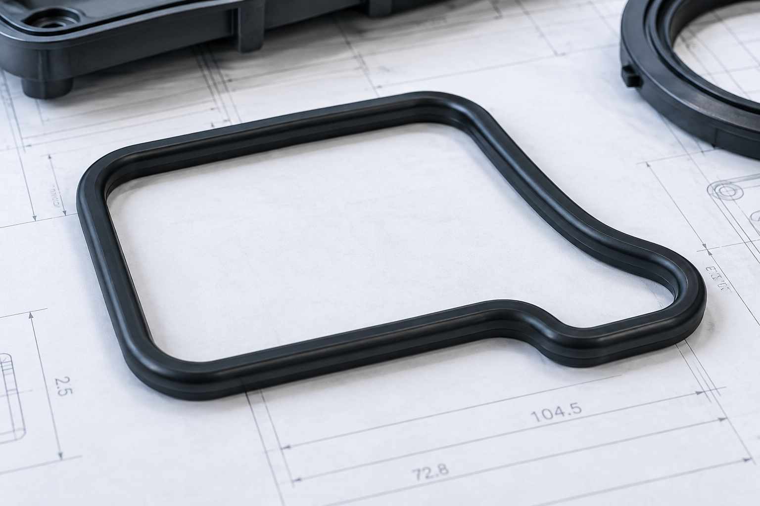
Sealing plastic parts often look simple, but they can be difficult to control in production.
A cover, tank, housing, valve body, or connector may pass visual inspection and still fail a leak test. In many cases, the real problem is not the gasket. It is the plastic part itself.
Poor flatness, local sink, uneven shrinkage, weld lines, or unstable molding conditions can all reduce sealing performance.
For this reason, good sealing performance must be controlled from part design, mold design, machining, molding, and final inspection.
Why Sealing Plastic Parts Are Difficult to Control
A sealing surface needs to stay stable after molding.
However, plastic parts shrink as they cool. Different areas may shrink at different rates.
This becomes more serious when the part has:
- Uneven wall thickness
- Large ribs
- Thick bosses
- Long sealing edges
- Glass fiber materials
- Large flat surfaces
- Uneven cooling
- Multiple gates
- Complex internal structures
A part can therefore look acceptable but still have a sealing surface that is slightly twisted.
For normal cosmetic parts, a small amount of warpage may not matter.
For sealing plastic parts, even a small flatness error can cause leakage.
Flatness Is One of the Most Important Requirements
Flatness directly affects how evenly the gasket or mating surface is compressed.
If one area is too high, another area may not receive enough pressure.
This can create a leak path.
For example, a plastic tank cover may use a rubber gasket around the full perimeter.
If the sealing surface has a 0.5 mm local deformation, the gasket may still look compressed in most areas. However, one corner may not have enough contact pressure.
The result can be:
- Water leakage
- Air leakage
- Pressure loss
- Uneven gasket compression
- Long-term seal failure
Therefore, flatness should be treated as a functional dimension, not only as a drawing number.
Sealing Plastic Parts Need Good Wall Thickness Design
Wall thickness has a major effect on shrinkage and warpage.
If one side of the sealing surface is much thicker than the other side, cooling will not be uniform.
The thicker area cools more slowly and normally shrinks more.
This can pull the sealing surface out of shape.
A better design should keep wall thickness as even as possible.
When thick structures cannot be avoided, designers can consider:
- Coring out thick areas
- Reducing rib thickness
- Changing boss design
- Adding smooth thickness transitions
- Adjusting local support structure
Good part design makes mold correction much easier later.
It also improves the stability of injection molding production.
Ribs and Bosses Can Pull the Sealing Surface
Ribs and bosses are common causes of sealing problems.
A boss may be needed for screws. Ribs may be added for strength.
However, both features create local material concentration.
If they are too thick, they can cause:
- Sink marks
- Local shrinkage
- Surface deformation
- Uneven cooling
- Flatness change
This is especially important when ribs or bosses are placed directly behind a sealing surface.
The front side may appear smooth, but the rear structure can still pull the sealing face inward.
At Fentor Mold, we normally review these areas carefully during DFM because correcting them in the mold later can be difficult.
Mold Cooling Strongly Affects Sealing Plastic Parts
Cooling is one of the biggest factors behind warpage.
If one side of the part cools much faster than the other side, the shrinkage becomes uneven.
Large sealing parts often need more attention because the sealing edge may run around the full perimeter.
Cooling channels should therefore be arranged as evenly as possible.
Special attention is often needed around:
- Deep cores
- Large inserts
- Thick corners
- Slider areas
- Boss clusters
- Long sealing edges
For some molds, copper alloy inserts or additional cooling circuits may be useful.
The goal is not only to shorten cycle time.
The more important goal is to keep the part shape stable.
Gate Position Can Change Flatness and Leak Performance
Gate design affects how the cavity fills and packs.
If the gate is poorly located, the pressure distribution may become uneven.
One side of the part may receive more packing pressure than another.
This can create uneven shrinkage after cooling.
For larger sealing plastic parts, Moldflow analysis can help compare different gate locations before cutting steel.
The analysis can help identify:
- Filling balance
- Pressure distribution
- Weld line position
- Packing behavior
- Warpage risk
- Air traps
However, simulation is only the first step.
The final result still needs to be confirmed by actual mold trials.
You can also review our injection mold capabilities for the tooling side of these projects.
Weld Lines Can Become Leak Paths
Weld lines are not always cosmetic defects.
In sealing applications, they may become weak points.
This is especially true when a weld line appears directly on:
- A sealing face
- A pressure area
- A thin wall
- A threaded connection
- A fluid channel
The strength of the weld line depends on material temperature, mold temperature, venting, flow length, and gate design.
Glass fiber materials may make the situation more difficult.
If possible, important sealing areas should avoid major weld lines.
When that is not possible, the mold and process should be optimized to improve weld strength.
Venting Is Important for Sealing Plastic Parts
Poor venting can create trapped air.
This may lead to:
- Burns
- Short shots
- Weak weld lines
- Surface defects
- Incomplete filling
For sealing areas, incomplete filling can be a serious problem.
Even a small local defect may create a leak path.
Vents should be placed at the actual end-of-fill areas.
Their depth also needs to match the material.
Too shallow, and the air cannot escape.
Too deep, and flash may appear.
This is why venting should be checked again during mold trials instead of relying only on the original mold design.
Mold Precision Matters Around the Sealing Surface
A good molding process cannot fully correct poor mold geometry.
The sealing surface itself must be machined accurately.
Important areas include:
- Parting line
- Shut-off surfaces
- Inserts
- Core alignment
- Slider position
- Sealing grooves
- Locating features
If several inserts form one continuous sealing surface, their height must be controlled carefully.
Even a small step between inserts may affect gasket contact.
This is especially important for larger molds.
Fentor Mold uses CNC, EDM, grinding, and final fitting together to control these areas before and after mold trials.
How to Control Flatness During Mold Trials
T1 should not only check whether the part can be filled.
For sealing plastic parts, flatness needs to be measured early.
A useful trial process should include:
- Run the mold until the process is stable.
- Keep samples from different cycles.
- Allow the parts to cool and stabilize.
- Measure the sealing surface.
- Compare several samples.
- Record the molding parameters.
- Perform a leak test when possible.
If the part is warped, the team should identify the cause before modifying steel.
Possible causes include:
- Cooling imbalance
- Packing pressure
- Gate position
- Ejection stress
- Part structure
- Material shrinkage
- Mold temperature
Changing steel too early can create a second problem.
Do Not Judge Flatness Immediately After Molding
Plastic parts can continue to change after ejection.
This is especially true for larger parts and engineering plastics.
A part may look flat when it is still warm.
Several hours later, the shape may change.
Therefore, measurement timing needs to be consistent.
For tight-tolerance projects, buyers and suppliers should agree on:
- Cooling time
- Storage condition
- Measurement time
- Fixture condition
- Inspection method
This makes the inspection result more reliable.
Leak Testing Should Match the Real Application
A leak test is only useful when the test method reflects the actual product requirement.
Common methods include:
- Air pressure test
- Water pressure test
- Vacuum test
- Pressure decay test
- Bubble test
The right method depends on the product.
For example, a low-pressure enclosure does not need the same test as a pressurized fluid tank.
The buyer should define:
- Test pressure
- Test time
- Allowed pressure drop
- Test medium
- Sample condition
- Number of samples
Without these conditions, the words “leak test passed” are too vague.
A Passing Leak Test Does Not Always Mean the Mold Is Stable
One sample can pass by chance.
Production stability is more important.
If ten parts are tested and only eight pass, the issue is not solved.
A stable mold should produce consistent sealing performance over time.
For multi-cavity molds, each cavity should also be checked separately.
This helps find problems such as:
- One cavity with poor venting
- One cavity with different cooling
- Insert height differences
- Uneven packing between cavities
Fentor Mold normally treats leak testing as part of the full validation process rather than as a final yes-or-no check.
Check the Gasket Groove Together With the Plastic Part
Not all leaks come from flatness.
The gasket groove itself can also create problems.
Important points include:
- Groove width
- Groove depth
- Corner radius
- Gasket compression
- Gasket position
- Surface finish
- Screw spacing
If the groove is too deep, the gasket may not compress enough.
If it is too shallow, the gasket may be over-compressed.
Both conditions can cause failure.
The plastic part and the sealing element should therefore be reviewed as one system.
Screw Position and Clamping Force Also Matter
Screw locations affect pressure around the sealing edge.
If screws are too far apart, the plastic can lift between them.
If the plastic wall is too flexible, the tightening force may also distort the part.
This is common with large covers.
A good design should balance:
- Screw spacing
- Boss strength
- Part stiffness
- Gasket compression
- Sealing surface flatness
The final assembly test is often more useful than checking the plastic part alone.
What Buyers Should Check Before Approving Sealing Plastic Parts
Before approval, buyers should confirm several items:
- Sealing surface flatness
- Critical dimensions
- Gasket groove size
- Screw positions
- Part warpage
- Weld line condition
- Flash on sealing areas
- Surface defects
- Leak test method
- Leak test result
- Multiple sample consistency
- Cavity-to-cavity consistency
For critical projects, these checks should be included in the final sample approval process.
You can also refer to our injection mold acceptance checklist when reviewing a mold before shipment.
Final Thoughts
Sealing plastic parts require more than a good gasket.
Flatness, wall thickness, cooling, gate design, mold accuracy, molding parameters, and final assembly all affect leak performance.
The most common mistake is to wait until the final leak test before checking these risks.
By then, mold changes may already be expensive.
A better approach is to control sealing performance from the beginning.
Review the part design. Protect the sealing surface. Balance cooling. Measure flatness during trials. Test several samples under realistic conditions.
When these steps are controlled together, sealing problems become much easier to prevent before mass production starts.