
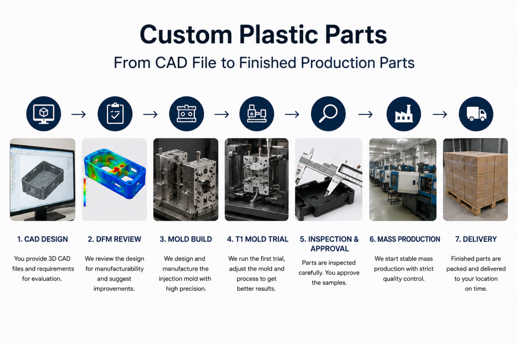
Custom plastic parts often begin with a finished CAD file, but turning that design into stable production parts is much more complicated than sending a 3D model to a factory.
A part may look complete on screen, yet still contain manufacturing risks involving wall thickness, draft angles, ribs, tolerances, gate location, shrinkage, material selection, or assembly fit. These issues usually become expensive only after mold manufacturing has already started.
A common situation is that the engineering team finishes the CAD model, the supplier provides a tooling quote, and the project appears ready to move forward. Then the DFM review begins.
Suddenly, questions appear: Can the part release from the mold? Will the ribs create sink marks? Are the tolerances realistic? Will the gate position cause warpage? Can the selected resin fill the geometry consistently?
For buyers sourcing custom plastic parts, this gap between product design and production reality is where many projects lose time and money.
The solution is not simply to “make a mold from the CAD file.”
A reliable manufacturing process converts the CAD model into a moldable design, validates the tooling through mold trials, confirms dimensional and cosmetic requirements, and stabilizes the process before full production begins.
This guide explains how custom plastic parts move from CAD files through DFM, mold manufacturing, T1 validation, quality approval, and finally into repeatable production.
What Are Custom Plastic Parts?
Custom plastic parts are plastic components manufactured to a customer’s specific geometry, material, dimensional and functional requirements rather than purchased as standard off-the-shelf items.
They may include:
- electronic housings
- equipment covers
- brackets
- clips
- connectors
- structural plastic components
- medical device housings
- automotive plastic parts
- industrial enclosures
- small precision components
- overmolded components
- insert-molded parts
The manufacturing method depends on quantity, geometry, material and application.
For a few prototypes, CNC machining or 3D printing may be sufficient.
For hundreds, thousands or millions of repeat parts, injection molding usually becomes more practical.
But the quality of the finished custom plastic parts depends heavily on decisions made before the first mold component is cut.
1. Start With the Correct CAD File
The 3D CAD model is usually the starting point for a custom plastic part project.
Common file formats include:
- STEP
- STP
- X_T
- Parasolid
- IGES
- native SolidWorks files
STEP or Parasolid files are usually preferable to STL files for mold development because they contain usable solid geometry rather than only a triangulated mesh.
However, sending only a 3D model is often not enough.
A manufacturer should also understand:
- critical dimensions
- tolerance requirements
- cosmetic surfaces
- mating components
- assembly interfaces
- material requirements
- annual production quantity
- expected mold life
- surface texture
- color requirements
- testing requirements
For this reason, the CAD model should normally be accompanied by a 2D engineering drawing when important dimensions or specifications cannot be communicated clearly through the 3D model alone.
This is also why preparing a complete RFQ package matters before asking a supplier to manufacture your injection mold.
2. Review the Part Before Building the Mold
One of the most expensive mistakes in custom plastic parts manufacturing is cutting steel before the part has been reviewed for manufacturability.
This review is normally called DFM — Design for Manufacturability.
A good DFM review looks beyond whether the geometry can theoretically be molded.
It asks whether the part can be molded repeatedly and economically.
Typical issues include:
Wall thickness
Large variations in wall thickness can create:
- sink marks
- internal stress
- different cooling rates
- warpage
- longer cycle times
Uniform walls are generally easier to mold consistently.
Draft angles
Vertical surfaces normally require draft so the molded part can release from the cavity or core without excessive friction.
Insufficient draft can cause:
- scratching
- drag marks
- ejection problems
- dimensional damage
- higher mold maintenance
Ribs and bosses
Ribs and screw bosses improve structural strength, but oversized ribs or thick intersections can cause visible sink marks on the opposite surface.
Undercuts
An undercut may require:
- sliders
- lifters
- collapsible cores
- unscrewing mechanisms
These features can significantly affect tooling cost and maintenance requirements.
Parting line
The parting line influences:
- cosmetics
- flash
- mold construction
- machining
- ejection
- dimensional control
These decisions should be reviewed before tooling starts, not after T1.
Our detailed Injection Mold Design Guide covers these design factors in greater depth.
3. Confirm the Plastic Material Before Tooling
Material selection is not just a purchasing decision.
Different plastics behave differently inside the mold.
Common materials for custom plastic parts include:
| Material | Typical Advantages | Common Applications |
|---|---|---|
| ABS | Good appearance, impact resistance | Housings, consumer products |
| PC | High impact strength, transparency options | Covers, electrical parts |
| PC/ABS | Balanced toughness and processability | Automotive and electronic housings |
| PP | Low density, chemical resistance | Containers, clips, industrial parts |
| PA66 | High strength and temperature resistance | Mechanical components |
| POM | Low friction, dimensional stability | Gears, moving parts |
| HDPE | Chemical and impact resistance | Industrial products |
| TPE/TPU | Flexible and soft-touch properties | Seals, grips, overmolding |
The exact resin grade is important.
For example, replacing a standard ABS with a glass-filled engineering resin can change:
- shrinkage
- gate requirements
- flow behavior
- mold wear
- surface appearance
- dimensional stability
This is why material should ideally be confirmed before final mold shrinkage and cavity dimensions are established.
4. Decide How the Part Will Be Gated
Molten plastic must enter the cavity somewhere.
That location can have a surprisingly large effect on the finished part.
Gate design influences:
- filling balance
- weld lines
- warpage
- pressure
- packing
- shrinkage
- visible gate marks
- automatic degating
For cosmetic housings, buyers often want the gate hidden.
But hiding the gate should not create a worse filling condition.
A visually convenient gate location can sometimes create:
- long flow lengths
- pressure loss
- poor packing
- uneven orientation
- dimensional distortion
The mold designer therefore has to balance cosmetics with molding performance.
For larger or more complex custom molded plastic parts, mold flow analysis may be useful before steel cutting.
5. Design the Mold Around Production Requirements
The same plastic part can be produced using very different molds.
A mold intended for 2,000 parts does not necessarily need the same construction as one intended for 1,000,000 parts.
Before tooling starts, buyers should define:
Expected production volume
This affects:
- mold steel
- number of cavities
- runner system
- mold base
- automation
- cooling design
- component life
Mold life requirement
A short-run mold may use different materials and standards than a high-volume production tool.
Single cavity or multi-cavity
More cavities can reduce unit cost but increase:
- mold cost
- mold size
- filling complexity
- cooling requirements
- validation requirements
Cold runner or hot runner
Hot runners can reduce runner waste and sometimes improve automation, but they also increase tooling cost and maintenance complexity.
A good manufacturer should design the tooling around the business case for the custom plastic parts, rather than automatically selecting the most complicated mold.
6. Manufacture the Injection Mold
Once the design is approved, mold manufacturing begins.
Typical operations include:
- purchasing mold steel
- rough CNC machining
- heat treatment where required
- precision CNC machining
- EDM
- wire EDM
- grinding
- fitting
- polishing or texturing
- assembly
- cooling-line testing
- final inspection
High-precision mold areas such as shutoffs, sliders, inserts and sealing surfaces require careful machining and fitting.
Small machining errors in the mold can eventually appear as:
- flash
- mismatch
- dimensional variation
- scratches
- sticking
- premature wear
The mold should therefore be treated as a production system rather than simply a machined block of steel.
7. Run the First Mold Trial
The first mold trial is commonly called T1.
T1 is not just an opportunity to see whether plastic comes out of the mold.
It is the first real test of the complete system:
- part design
- mold design
- material
- filling
- cooling
- venting
- ejection
- dimensions
- appearance
During the trial, engineers normally adjust variables such as:
- melt temperature
- mold temperature
- injection speed
- injection pressure
- holding pressure
- holding time
- cooling time
The objective is to establish whether acceptable custom plastic parts can be produced under a reasonable and repeatable process window.
You can see the typical validation sequence in our Injection Mold Trial Process.
8. Measure the T1 Parts, Not Just Look at Them
A part can look excellent and still fail assembly.
That is especially common with housings, covers and precision structural components.
T1 evaluation should include dimensions such as:
- overall length and width
- flatness
- hole position
- boss spacing
- mating features
- snap-fit dimensions
- critical wall thickness
- sealing surfaces
For tight-tolerance custom plastic parts, measurements should ideally be made after the parts have reached a stable condition rather than immediately after molding.
Some plastics continue to shrink or absorb moisture after molding.
The supplier and buyer should agree in advance on:
- measuring method
- measurement temperature
- conditioning requirements
- datum system
- critical dimensions
9. Correct Problems Before Mass Production
Very few complex injection molds should be judged purely on the first trial.
T1 can reveal problems that were difficult to predict completely during design.
Examples include:
Sink marks
Possible corrections:
- reduce local thickness
- modify rib dimensions
- improve packing
- change gate size
- improve cooling
Warpage
Possible corrections:
- rebalance cooling
- change packing conditions
- adjust gate location
- modify part geometry
- compensate mold dimensions
Flash
Possible corrections:
- improve mold fitting
- reduce excessive injection pressure
- correct shutoff surfaces
- increase mold rigidity
Dimensional deviation
Possible corrections:
- adjust process settings
- modify inserts
- compensate steel dimensions
The important point is to determine whether the root cause comes from:
the part design, the mold or the molding process.
Changing steel before understanding the cause can make the problem worse.
10. Approve a Golden Sample
Once dimensions, appearance and assembly are acceptable, the buyer should approve representative production samples.
These are often called:
golden samples or master samples.
A golden sample gives both sides a physical reference for future production.
Depending on the product, the approval package may also include:
- dimensional report
- material certificate
- color reference
- surface texture requirement
- assembly test
- functional test
- approved process parameters
This helps prevent disagreements later when mass production begins.
11. Establish a Stable Production Process
A successful mold trial does not automatically guarantee stable production.
The next step is establishing a repeatable molding window.
The manufacturer should control parameters such as:
- material drying
- barrel temperature
- mold temperature
- injection speed
- transfer position
- holding pressure
- cooling time
- cycle time
The goal is not to find one perfect machine setting.
It is to find a stable operating range where the process consistently produces acceptable parts.
For customers requiring ongoing supply rather than only tooling, this transition from mold development into injection molding production is especially important.
12. Define Quality Control for Production Parts
Quality requirements should match the function of the part.
Not every dimension needs an extremely tight tolerance.
Over-specifying tolerances can:
- increase tooling cost
- increase inspection cost
- create unnecessary rejects
- make the molding process harder to control
Instead, identify dimensions that affect:
- assembly
- sealing
- mechanical performance
- alignment
- safety
- appearance
Typical production quality control may include:
- first-piece inspection
- dimensional sampling
- visual inspection
- weight monitoring
- color inspection
- assembly testing
- functional testing
- CMM inspection
- fixture inspection
For tighter dimensional applications, our guide to injection molding tolerances explains what buyers should realistically specify.
13. Plan Secondary Operations Before Production Starts
Injection molding may not be the final manufacturing step.
Many custom plastic parts need secondary operations such as:
- ultrasonic welding
- heat staking
- threaded insert installation
- pad printing
- screen printing
- laser marking
- painting
- assembly
- adhesive bonding
These processes should be considered during product and mold design.
For example, if threaded inserts will be heat-installed after molding, the boss geometry must provide enough plastic around the insert.
If two housing halves will be ultrasonically welded, the joint design must include suitable energy-director geometry.
Designing the molding process without considering downstream assembly can create avoidable production problems.
14. Package the Parts According to the Surface Requirement
Packaging is often underestimated.
A mechanically strong industrial component may only require simple bulk packaging.
A high-gloss housing or transparent part may require:
- protective film
- individual bags
- trays
- separators
- controlled stacking
Otherwise acceptable custom plastic parts can become unusable because of scratches during transport.
Packaging specifications should therefore be agreed before mass production rather than after the first shipment is damaged.
From CAD to Finished Custom Plastic Parts: Typical Workflow
A well-controlled project usually follows this sequence:
3D CAD
↓
Engineering drawing and specifications
↓
DFM review
↓
Material confirmation
↓
Mold design
↓
Tool manufacturing
↓
T1 mold trial
↓
Dimensional and cosmetic inspection
↓
Mold correction
↓
T2 / validation
↓
Golden sample approval
↓
Stable injection molding process
↓
Mass production
↓
Quality inspection
↓
Secondary operations
↓
Packaging and shipment
Skipping one of these stages may save a few days early in the project, but it can create much larger delays later.
What Should You Send a Manufacturer Before Requesting Custom Plastic Parts?
For a useful quotation, prepare as much of the following information as possible:
| Information | Why It Matters |
|---|---|
| 3D CAD file | Defines part geometry |
| 2D drawing | Defines tolerances and critical dimensions |
| Plastic material | Affects shrinkage, tooling and process |
| Color | Affects resin and cosmetic requirements |
| Surface finish | Affects polishing/texturing |
| Annual quantity | Determines mold strategy |
| Order quantity | Helps calculate part pricing |
| Mold life | Affects steel and tooling construction |
| Critical dimensions | Defines quality priorities |
| Cosmetic surfaces | Helps determine gate and parting-line location |
| Assembly information | Helps identify mating risks |
| Packaging requirements | Prevents shipping damage |
The more clearly these requirements are defined, the more accurately the supplier can evaluate the tooling and production process.
Should You Prototype Before Building a Production Mold?
Not every project needs a molded prototype.
A prototype may be useful when you still need to validate:
- assembly
- ergonomics
- overall dimensions
- appearance
- functional fit
3D printing and CNC machining can often answer these questions before production tooling.
However, prototypes made by another process cannot always predict:
- injection molding shrinkage
- weld lines
- sink marks
- gate appearance
- mold-induced warpage
If molded material behavior is important, a prototype or low-volume injection mold may be more representative.
The correct approach depends on what uncertainty you are trying to eliminate.
Choosing a Manufacturer for Custom Plastic Parts
A supplier should be able to do more than operate an injection molding machine.
For a new product, buyers should evaluate whether the manufacturer can manage:
DFM
Can the supplier identify molding risks before tooling starts?
Mold engineering
Can the supplier explain why a particular gate, cooling layout or mold structure is being used?
Tool manufacturing
Does the supplier control critical mold machining and fitting?
Mold trials
Are T1 results documented and analyzed?
Dimensional inspection
Can the supplier measure the features that actually matter to your assembly?
Production molding
Can the same supplier take the project from tooling into repeat production?
Problem solving
When a molded part fails, can the supplier distinguish between a design problem, mold problem and process problem?
For overseas buyers, these capabilities often matter more than choosing the lowest mold quotation.
Final Thoughts
Producing custom plastic parts is not simply a matter of sending a CAD file to a factory and waiting for finished components.
The CAD file is only the starting point.
A reliable project requires the product design, mold design, plastic material, molding process, dimensional requirements and downstream assembly to work together.
When these decisions are reviewed early, the project is much more likely to move smoothly from:
CAD → tooling → T1 → approval → production.
When they are not, problems that appear small during design can become expensive steel changes, repeated mold trials and production delays.
For engineering and procurement teams, the best time to solve those problems is before the mold is built—not after the first shipment.