
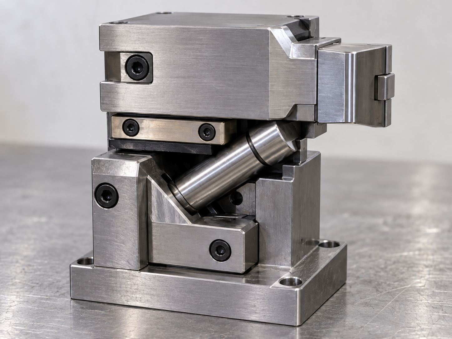
An injection mold heel block is a key part of the slider locking system. Its main job is to hold the slider firmly in position during injection.
If the heel block does not lock the slider correctly, cavity pressure can push the slider backward.
As a result, the mold may produce flash, parting-line steps, dimensional errors, or even slider damage.
Therefore, heel block design should not be treated as a small detail. The contact angle, locking surface, steel strength, machining accuracy, and wear condition all affect slider stability.
At Fentor Mold, we check the heel block together with the slider, angle pin, wear plate, and locking surface to make sure the complete mechanism works safely.
What Is an Injection Mold Heel Block?
An injection mold heel block is a fixed locking component that supports the slider when the mold is closed.
The angle pin moves the slider during mold opening and closing. However, the angle pin should not carry the full injection pressure during molding.
Instead, the heel block provides the main locking force.
A typical slider system may include:
- Slider body
- Angle pin
- Heel block
- Wear plate
- Gibs or guide rails
- Slider insert
- Springs or hydraulic components
- Limit switch or position sensor
When the mold closes, the heel block contacts the back or angled surface of the slider.
This contact prevents the slider from moving backward during injection.
Why Injection Mold Heel Block Design Matters
The slider may look fully closed, but high cavity pressure can still push it backward.
This is especially common when the slider forms:
- Large side holes
- Deep undercuts
- Large side walls
- Sealing surfaces
- Cosmetic shutoffs
- High-pressure cavity areas
If the injection mold heel block is too weak or does not contact properly, the slider may move slightly during filling or packing.
Even a small movement can create visible defects.
| Heel Block Problem | Possible Result |
|---|---|
| Poor contact | Slider movement |
| Worn locking surface | Flash |
| Weak heel block | Deformation |
| Wrong locking angle | High side force |
| Insufficient support | Slider shifts backward |
| Surface damage | Unstable locking |
| Loose heel block | Misalignment |
Therefore, slider locking should be checked under actual molding pressure, not only during manual assembly.
How Injection Mold Heel Block Prevents Slider Movement
The injection mold heel block works by transferring cavity pressure into the mold base.
When the slider receives pressure from molten plastic, that force tries to push the slider outward.
The heel block resists this movement.
A good locking system should create:
Cavity pressure → Slider → Heel block → Mold plate
This load path is important.
If the heel block does not contact correctly, the angle pin or guide surface may receive unwanted force.
As a result, wear increases and slider movement becomes less stable.
Injection Mold Heel Block Contact Must Be Correct
Good contact between the heel block and slider is critical.
The locking surfaces should contact evenly when the mold is fully closed.
Poor contact may appear as:
- Contact only at the top
- Contact only at the bottom
- Small local contact area
- Uneven wear marks
- Gap between locking surfaces
- Edge contact only
If only a small area carries the load, pressure becomes concentrated.
As a result, the surface can wear or deform faster.
Therefore, the contact area should be checked during mold fitting and spotting.
Heel Block Angle and Slider Locking
The locking angle affects how force transfers through the injection mold heel block.
If the angle is too aggressive, the slider may receive excessive side force.
If the angle is too weak, the heel block may not provide enough support.
The correct design depends on:
- Slider size
- Injection pressure
- Locking area
- Steel strength
- Slider stroke
- Available mold space
The goal is stable contact and reliable force transfer.
Therefore, the angle should be selected together with the complete slider structure.
Do Not Use the Angle Pin as the Main Lock
One common mistake is relying too much on the angle pin.
The angle pin should mainly move the slider.
It should not be expected to hold high injection pressure by itself.
If the heel block has poor contact, the slider can push against the angle pin during injection.
This may cause:
- Bent angle pin
- Worn angle pin hole
- Slider movement
- Enlarged clearance
- Difficult mold opening
- Premature slider failure
Therefore, a proper injection mold heel block should carry the locking force.
What Causes Injection Mold Heel Block Wear?
Heel blocks experience repeated contact during every mold cycle.
Over time, wear can develop.
Common causes include:
- Poor lubrication
- Small contact area
- Soft steel
- Incorrect hardness
- Slider misalignment
- High injection pressure
- Uneven locking force
- Rough surface finish
- Poor fitting
In addition, dirt or metal particles between the locking surfaces can create scratches.
Once wear starts, the contact condition may become worse.
As a result, slider movement increases.
Signs of Injection Mold Heel Block Wear
Heel block wear is not always obvious at first.
Technicians may notice:
- Flash near the slider area
- Parting-line step
- Slider noise
- Uneven wear marks
- Loose slider position
- Slider surface scratches
- Increased clearance
- Product dimension changes
For example, if flash appears only near one side of the slider, the locking surface should be checked.
The problem may not come from the cavity parting surface.
Instead, the slider may be moving backward during injection.
Injection Mold Heel Block Steel Selection
Steel selection affects wear resistance and long-term stability.
A heel block should have enough:
- Strength
- Hardness
- Wear resistance
- Toughness
If the steel is too soft, the locking surface may dent or wear quickly.
However, very hard steel can also become brittle if the design creates strong impact.
Therefore, steel selection should match the mold life and locking force.
The contact surface may also require heat treatment or surface hardening.
At Fentor Mold, the steel and hardness are selected according to slider size, load, production volume, and maintenance requirements.
Use Wear Plates Where Needed
Large sliders often use wear plates.
The wear plate can protect the slider and mold base from repeated sliding contact.
It can also make maintenance easier.
If the wear surface becomes damaged, technicians can replace the plate instead of repairing the main slider body.
This is especially useful for:
- Large sliders
- Heavy sliders
- Long production molds
- High-speed molds
- High-load mechanisms
However, the wear plate must also remain flat and secure.
Loose wear plates can affect slider alignment and heel block contact.
Injection Mold Heel Block and Slider Clearance
Slider clearance must be controlled carefully.
Too much clearance allows movement.
Too little clearance can cause jamming.
Therefore, the slider should move smoothly during opening and closing while remaining stable during injection.
The heel block helps control the locked position.
If the slider clearance increases after long production, the heel block may no longer contact correctly.
As a result, the slider may shift.
For repeated slider movement problems, the complete mechanism should be checked, not only the heel block.
You can also review our article on injection mold slide jamming for related slider wear and alignment problems.
Support the Heel Block Properly
A strong heel block can still fail if the structure behind it is weak.
The heel block should transfer force into a solid mold plate or insert.
If the supporting area deforms, the locking position can change.
Therefore, designers should check:
- Plate thickness
- Heel block seating area
- Screw strength
- Dowel location
- Back support
- Local steel thickness
This is especially important for large sliders.
If the surrounding mold plate flexes, the slider may still move even when the heel block itself is strong.
Fix the Heel Block Securely
The heel block should not depend only on screws for position.
For high-load structures, dowels or machined locating surfaces can help control movement.
The screws mainly provide clamping force.
Locating features help resist side load.
This is important because repeated impact can loosen screws over time.
If heel block screws become loose, the locking position may change.
Therefore, technicians should check both screw tightness and locating accuracy during maintenance.
Injection Mold Heel Block Machining Accuracy
Machining accuracy directly affects locking performance.
Important dimensions include:
- Locking angle
- Contact surface
- Heel block position
- Slider position
- Screw location
- Dowel location
- Back support
Even a small error can reduce the real contact area.
Therefore, finish machining and fitting should be completed carefully.
For precision molds, final contact should be verified after assembly.
How to Check Injection Mold Heel Block Contact
Technicians can inspect the heel block during mold fitting.
A simple process may include:
- Clean the slider and heel block.
- Close the mold slowly.
- Check the contact surface.
- Observe contact marks.
- Correct uneven high spots.
- Repeat until contact is stable.
The goal is not maximum contact everywhere.
Instead, the goal is stable and sufficient load-bearing contact.
After mold trial, wear marks should also be reviewed.
Slider Movement During Injection
Sometimes the slider looks correct during assembly but moves only during production.
This usually means the locking system cannot resist cavity pressure.
Possible causes include:
- Heel block wear
- Weak heel block support
- Poor contact
- High injection pressure
- Loose screws
- Slider clearance
- Plate deformation
Therefore, technicians should compare defects under different molding pressures.
For example:
| Process Change | What to Observe |
|---|---|
| Lower packing pressure | Does flash decrease? |
| Higher injection pressure | Does slider-area flash increase? |
| Longer holding pressure | Does the defect become worse? |
| Lower speed | Does movement reduce? |
If the defect changes clearly with pressure, the slider locking system should be checked.
Injection Mold Heel Block for Large Sliders
Large sliders need more locking strength.
They often have:
- Larger projected area
- Higher cavity pressure load
- Greater weight
- Longer movement
- More wear surface
Therefore, the injection mold heel block may need a larger contact area.
In some molds, one heel block is not enough.
Several locking surfaces may be used to distribute the load.
This reduces local stress and improves stability.
Add Secondary Slider Protection
For complex or expensive molds, mechanical locking alone may not be enough.
Position confirmation can add another safety layer.
For example, a limit switch can confirm that the slider has reached its correct position before injection begins.
If the slider is not fully closed, the machine should stop.
This does not replace the heel block.
However, it helps prevent mold damage caused by incomplete slider movement.
Injection Mold Heel Block Maintenance Checklist
Regular inspection can detect wear before it causes production defects.
| Inspection Item | What to Check |
|---|---|
| Heel block surface | Wear and dents |
| Slider locking surface | Contact condition |
| Locking angle | Damage or deformation |
| Screws | Tightness |
| Dowels | Position and wear |
| Wear plates | Wear and looseness |
| Slider clearance | Excessive movement |
| Lubrication | Correct condition |
| Support plate | Local deformation |
| Molded parts | Flash near slider |
The inspection frequency depends on mold size, production cycles, pressure, and slider load.
Repair or Replace a Worn Heel Block?
Light wear may sometimes be corrected by grinding or fitting.
However, heavy wear usually requires replacement.
Replacement is recommended when:
- Locking surface is deeply worn
- Heel block is cracked
- Contact cannot be restored
- Geometry has changed
- Repeated repairs have failed
- Slider movement continues
Do not simply remove too much steel from the locking surface.
This may increase slider clearance and make the problem worse.
Final Thoughts
An injection mold heel block plays a critical role in preventing slider movement during injection.
It provides the locking force that resists cavity pressure and keeps the slider in the correct position.
However, reliable locking depends on more than the heel block itself.
Contact area, locking angle, steel hardness, slider clearance, plate support, machining accuracy, and maintenance all work together.
If the slider moves during injection, do not immediately blame the parting surface.
Instead, check the complete locking system.
At Fentor Mold, we review the heel block, slider, wear plate, angle pin, support structure, and contact condition together. A stable locking system can reduce flash, improve dimensional consistency, and protect the mold from long-term wear.