
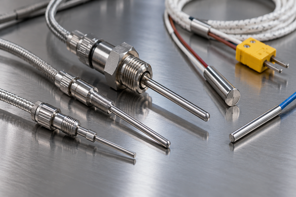
Mold temperature sensors help engineers monitor heat inside an injection mold. Proper sensor placement can reveal hot spots, uneven cooling, and temperature changes that affect plastic part quality.
However, installing a sensor in the wrong location may produce misleading readings. The mold temperature controller may show a stable value while the actual cavity surface is too hot or too cold.
At Fentor Mold, we consider mold temperature sensors during the mold design process when accurate thermal monitoring is required. The right sensor location can help engineers improve cooling performance, reduce warpage, and maintain stable production.
This guide explains where to place injection mold temperature sensors, which types to choose, and how to avoid common installation mistakes.
What Are Mold Temperature Sensors?
Mold temperature sensors are devices that measure temperature at selected points inside or on an injection mold.
They help engineers understand how the mold heats up and cools down during production.
Temperature sensors can monitor:
- Mold cavity surface temperature
- Core and cavity insert temperature
- Temperature near cooling channels
- Hot spots in thick sections
- Temperature differences between mold halves
- Cooling circuit inlet and outlet temperatures
However, not every sensor measures the same thing.
For example, a sensor embedded inside the mold steel measures the temperature at its installation depth. A flush-mounted cavity sensor measures conditions much closer to the plastic contact surface.
Therefore, engineers must select the sensor according to the measurement goal.
For more information about the overall process, read our guide to Mold Temperature Control in Injection Molding.
Types of Mold Temperature Sensors
Several types of sensors are used in injection molding. Each has different advantages and installation requirements.
1. Thermocouple Temperature Sensors
Thermocouples are widely used for industrial temperature measurement.
They produce a small electrical signal when the temperature changes. A suitable controller then converts this signal into a temperature reading.
Common thermocouple types include Type K and Type J.
Their advantages include:
- Compact size
- Fast response when properly designed
- Wide temperature range
- Relatively low cost
- Easy connection to monitoring equipment
Thermocouples can be installed in drilled holes or special sensor pockets.
However, the sensor tip must have good thermal contact with the area being measured.
Poor contact can cause slow or inaccurate readings.
2. RTD Mold Temperature Sensors
Resistance Temperature Detectors, or RTDs, measure temperature through changes in electrical resistance.
Pt100 and Pt1000 are common examples.
RTDs often provide good accuracy and repeatability when used within their rated temperature range.
They are useful for monitoring relatively stable mold temperatures.
However, many RTD assemblies are larger or slower than small thermocouples.
Therefore, they may not be the best choice for very fast cavity temperature changes.
3. Infrared Temperature Sensors
Infrared sensors measure thermal radiation.
Some specialized in-mold infrared sensors can monitor temperature during the injection molding cycle.
They can provide useful information about the melt or the cavity surface, depending on the sensor design and optical arrangement.
However, infrared measurement requires careful installation and calibration.
The sensor must also suit the plastic material and measurement conditions.
For this reason, infrared sensors are generally more specialized than standard embedded thermocouples.
4. Flush-Mounted Cavity Temperature Sensors
Flush-mounted sensors sit at or very close to the cavity surface.
Their main purpose is to measure local thermal changes during molding.
For example, they can detect the arrival of the melt flow front through a rapid temperature rise.
They can also help engineers study cooling differences between selected cavity locations.
However, a cavity thermocouple does not necessarily measure the true bulk melt temperature.
Heat transfer into the surrounding mold steel affects its reading.
Therefore, engineers should understand the sensor’s measurement method before using the data for process control.
Where to Place Mold Temperature Sensors
Mold temperature sensors should be installed where temperature data can help engineers make decisions.
The best location depends on part geometry, cooling design, material properties, and the problems being investigated.
1. Near the Cavity Surface
The cavity surface directly affects how molten plastic cools.
Therefore, this is one of the most useful locations for mold temperature sensors.
A sensor close to the cavity surface can help monitor:
- Local temperature changes
- Cooling consistency
- Thermal conditions before injection
- Temperature changes after cycle interruptions
- Differences between production cycles
However, sensor depth matters.
A sensor buried deep inside the steel responds differently from one located close to the cavity wall.
For accurate cavity surface measurement, engineers should select a suitable flush-mounted sensor or a validated installation depth.
There is no universal sensor depth that works for every mold.
The correct position depends on the sensor design, cavity geometry, and remaining steel thickness.
2. Near Thick-Walled Areas
Thick plastic sections usually retain heat longer than thin sections.
As a result, these areas may develop hot spots or cool more slowly.
This can contribute to:
- Sink marks
- Warpage
- Dimensional changes
- Longer cooling time
- Uneven shrinkage
Placing a temperature sensor near a thick section can help engineers track local thermal behavior.
For example, an automotive plastic housing may have thick mounting bosses and reinforcing ribs.
These features can create uneven cooling.
A sensor near the critical area may help identify the temperature difference.
However, the sensor should not weaken the mold insert or interfere with cooling channels.
3. Near Cooling Channels
Cooling channels remove heat from the mold.
Therefore, sensor placement near these channels can help evaluate heat transfer.
For example, engineers may place sensors in selected areas between the cavity surface and the cooling circuit.
These readings can help identify:
- Poor cooling performance
- Unbalanced cooling circuits
- Local temperature changes
- Possible cooling restrictions
- Differences between mold sections
However, a sensor placed directly beside a cooling channel may mainly reflect the local coolant-side temperature.
It may not represent the actual cavity surface temperature.
Therefore, sensor distance must match the intended measurement.
If cooling performance becomes unstable, also check the water flow and channel condition.
Our article on Injection Mold Cooling Channels explains how cooling restrictions affect mold temperature.
4. Inside the Core and Cavity Inserts
Core and cavity inserts can have different thermal conditions.
This is especially common in molds with deep cores, thick features, or limited cooling space.
For example, a deep core may retain heat because cooling channels cannot reach every area.
Installing mold temperature sensors in critical inserts can help track these conditions.
Engineers should consider:
- Insert thickness
- Available installation space
- Cooling channel location
- Sensor accessibility
- Wire routing
- Future mold maintenance
However, sensor holes must not weaken thin inserts.
In some cases, a sensor in the surrounding mold plate may be safer, although it provides a less direct measurement.
5. On Both Mold Halves
The fixed and moving mold halves may operate at different temperatures.
This can happen because of cooling circuit layout, core geometry, or contact conditions.
As a result, one side of the molded part may cool faster than the other.
This temperature difference can contribute to part warpage.
Therefore, installing mold temperature sensors on both halves can be useful for precision molding.
For example, two sensors placed at comparable thermal locations may help engineers identify differences between the core and cavity sides.
However, the readings must be compared under the same production conditions.
6. Near the Gate and End-of-Fill Area
Gate locations and end-of-fill areas can experience different thermal conditions.
A sensor near the gate may detect the arrival of hot plastic early in the filling process.
Meanwhile, a sensor near the end of the flow path may help identify when melt reaches that location.
These measurements can support:
- Flow-front detection
- Filling sequence analysis
- Valve gate control
- Process consistency checks
- Troubleshooting short shots
However, the sensor must be designed for this purpose.
A standard thermocouple buried deep in the mold may not respond quickly enough to detect melt arrival.
For flow-front monitoring, engineers should use suitable fast-response cavity sensors.
Mold Temperature Sensor Placement Guide
The following table summarizes common installation locations and their purposes.
| Sensor Location | Main Purpose | Key Consideration |
|---|---|---|
| Near cavity surface | Monitor local cavity temperature | Sensor depth and thermal response |
| Thick-walled part area | Identify hot spots | Avoid weakening the insert |
| Near cooling channels | Evaluate local cooling | Do not confuse coolant-side and cavity temperatures |
| Core insert | Monitor difficult cooling areas | Limited installation space |
| Fixed and moving halves | Compare thermal balance | Use comparable measurement points |
| Near gate | Detect early melt arrival | Requires fast-response sensor |
| End-of-fill area | Monitor flow-front arrival | Correct sensor type and location |
| Cooling water inlet and outlet | Monitor coolant temperature | Water temperature is not cavity temperature |
The best mold temperature sensor placement depends on the problem the engineer wants to solve.
Therefore, sensor locations should be planned before drilling the mold.
How Close Should Mold Temperature Sensors Be to the Cavity?
There is no single recommended distance for every mold.
The ideal sensor position depends on several factors.
Sensor Type
A flush-mounted cavity sensor may sit directly at the cavity surface.
However, an embedded thermocouple usually sits below the surface.
These sensors provide different measurements.
Mold Steel Thickness
Sensor holes must leave enough steel to support cavity pressure and mold strength.
A sensor placed too close to a thin wall may weaken the insert.
Therefore, engineers must review the mold structure before machining.
Cooling Channel Distance
A sensor located near a cooling channel may respond more strongly to coolant temperature.
However, a sensor near the cavity surface may provide better information about the thermal conditions experienced by the molded part.
The correct location depends on the measurement goal.
Required Response Time
A deeply embedded sensor responds more slowly to rapid surface temperature changes.
As a result, it may be suitable for monitoring overall mold temperature but less suitable for detecting individual filling events.
For fast process monitoring, a specialized cavity sensor may be required.
Benefits of Mold Temperature Sensors
Properly installed mold temperature sensors can improve process monitoring and support better molding decisions.
However, sensors do not automatically correct cooling problems. They provide data that engineers can use to improve the process.
1. Improve Temperature Stability
Temperature changes can affect plastic flow, shrinkage, and cooling.
With reliable sensor data, engineers can identify unusual temperature changes during production.
For example, a sensor may show that one mold area becomes hotter after the cycle time changes.
This allows the production team to investigate the cause before the problem becomes serious.
2. Reduce Warpage and Dimensional Variation
Uneven cooling can create different shrinkage rates across a molded part.
As a result, the part may warp after ejection.
Mold temperature sensors can help engineers identify thermal differences between critical mold areas.
They can then review cooling flow, mold temperature settings, or cooling channel design.
However, sensor data should be evaluated together with part dimensions and molding conditions.
3. Detect Cooling Problems Earlier
Blocked cooling channels can reduce heat transfer.
When this happens, local mold temperatures may gradually increase.
Temperature sensors may detect this change before operators notice severe part defects.
However, high temperature alone does not prove that a channel is blocked.
Engineers should also check water flow, pressure, and inlet and outlet temperatures.
4. Support Stable Cycle Time
Cooling time has a major effect on injection molding productivity.
If the mold temperature becomes unstable, operators may need longer cooling time to maintain part quality.
Temperature monitoring helps engineers understand whether the mold has reached stable operating conditions.
This is useful after machine stops, mold changes, or process adjustments.
However, reducing cycle time must not compromise part cooling or dimensional stability.
5. Improve Production Quality Monitoring
For precision plastic parts, small changes in mold temperature can affect final dimensions.
This is especially important for semi-crystalline plastics such as PP, PA, and POM.
Temperature monitoring can help identify changes that may affect shrinkage and part performance.
However, temperature data alone cannot guarantee good parts.
It should form part of a wider process control system that also monitors pressure, filling, cooling, and part quality.
Common Mold Temperature Sensor Installation Mistakes
Even a high-quality sensor can provide poor data when installed incorrectly.
The following mistakes should be avoided.
1. Installing Sensors Too Far from the Cavity
A sensor placed deep inside the mold plate may not reflect rapid cavity surface temperature changes.
As a result, the reading may look stable while the cavity surface changes significantly.
Therefore, engineers should select the installation depth based on the required measurement.
2. Poor Contact Between Sensor and Mold Steel
An embedded sensor needs good thermal contact.
Air gaps or poorly machined sensor pockets can slow the response.
They may also affect measurement accuracy.
Therefore, sensor holes and mounting surfaces should meet the sensor manufacturer’s installation requirements.
3. Installing Sensors Too Close to Cooling Water
A sensor near a water channel may mainly reflect the local cooling condition.
This can be useful for cooling studies.
However, it may not provide a reliable estimate of cavity surface temperature.
Therefore, the purpose of the measurement must be clear before choosing the location.
4. Ignoring Sensor Wire Protection
Sensor wires can be damaged during mold assembly, maintenance, or production.
Common risks include:
- Pinched cables
- Sharp edges
- Moving mold components
- Excessive bending
- High-temperature contact
- Poor connector protection
Therefore, wire routing should be included in the mold design.
Where possible, use protected channels and accessible connectors.
5. Using the Wrong Sensor Type
Not every temperature sensor can detect rapid changes during injection.
For example, a large embedded sensor may work well for monitoring slow temperature changes.
However, it may be unsuitable for detecting melt flow-front arrival.
Therefore, engineers should match the sensor type to the monitoring task.
How to Install Mold Temperature Sensors
A good installation process starts during mold design.
The following steps can reduce measurement errors and future maintenance problems.
Step 1: Define the Measurement Goal
First, decide what the sensor must measure.
For example:
- Cavity surface temperature
- Core temperature
- Cooling performance
- Local hot spots
- Melt arrival
- Temperature differences between cavities
The measurement goal determines the sensor type and location.
Step 2: Review the Mold Design
Check the mold structure before selecting the installation point.
Important areas include:
- Cavity and core inserts
- Cooling channels
- Ejector pins
- Screws and guide components
- Moving mechanisms
- Available steel thickness
The sensor must not interfere with normal mold operation.
Step 3: Select the Sensor Type
Choose a sensor with the correct:
- Temperature range
- Response time
- Diameter
- Accuracy
- Mounting method
- Cable protection
- Controller compatibility
Also, consider whether the sensor will remain inside the mold during production.
Step 4: Machine the Sensor Hole
Follow the sensor manufacturer’s installation dimensions and tolerances.
For embedded sensors, a correctly sized pocket helps ensure good thermal contact.
For flush-mounted cavity sensors, the sensor face must match the cavity geometry.
Poor installation may leave marks on the molded part or affect measurement accuracy.
Step 5: Protect the Sensor Wiring
Route cables away from moving components and sharp edges.
Where necessary, provide a protected cable channel.
Also, leave enough access for future sensor replacement.
Step 6: Test the Sensor During Mold Trials
After installation, check the readings during mold testing.
Compare the results with other available measurements.
Also, observe how the sensor responds during startup, stable production, and cycle interruptions.
This helps confirm that the sensor provides useful data.
When Should You Use Multiple Mold Temperature Sensors?
One sensor may be enough for basic monitoring of a simple mold.
However, complex molds often benefit from several measurement points.
Multiple sensors are particularly useful for:
- Large automotive plastic parts
- Multi-cavity injection molds
- Parts with thick and thin sections
- Deep cores with limited cooling
- Precision engineering plastic components
- Molds with several independent cooling circuits
For example, consider a large automotive housing with thick mounting bosses.
One sensor near the central cavity may show a stable temperature.
However, the area around a thick boss may remain much hotter.
A second sensor near that critical feature can help identify the difference.
Similarly, a multi-cavity mold may need temperature monitoring at selected cavities to evaluate cooling consistency.
The goal is not to install as many sensors as possible.
Instead, engineers should place sensors where the data can support a useful decision.
Mold Temperature Sensors vs. Temperature Controllers
Mold temperature sensors and mold temperature controllers perform different functions.
A temperature controller regulates the temperature of the circulating heating or cooling medium.
However, the controller display does not always show the actual cavity surface temperature.
For example, the controller may maintain water at a constant temperature.
Meanwhile, the mold core may still develop a hot spot because of thick steel, limited cooling, or poor water flow.
Therefore, both measurements can be useful.
| Feature | Mold Temperature Sensor | Mold Temperature Controller |
|---|---|---|
| Main function | Measures temperature at a selected point | Regulates circulating medium temperature |
| Measurement location | Mold steel, cavity surface, or coolant line | Usually coolant circuit or controller |
| Local hot spot detection | Possible with suitable placement | Limited |
| Thermal trend monitoring | Yes, with data logging | Usually monitors control circuit conditions |
| Controls heating and cooling | Only when linked to a control system | Yes |
| Best application | Local temperature monitoring and diagnosis | Overall mold heating and cooling management |
For reliable production, engineers should understand what each temperature reading represents.
How Fentor Mold Plans Temperature Sensor Placement
At Fentor Mold, we consider temperature monitoring together with mold design, cooling layout, and part quality requirements.
Not every injection mold needs built-in temperature sensors. However, they can provide useful data for projects with demanding thermal conditions.
During injection mold design and manufacturing, we review several factors.
Part Geometry
Thick walls, ribs, bosses, and deep cores can create uneven cooling.
These areas may need closer temperature monitoring.
Cooling Channel Layout
We consider how cooling channels remove heat from the cavity and core.
Sensor positions should support the cooling design rather than interfere with it.
Mold Structure
Available steel thickness, inserts, screws, and ejector systems affect where sensors can be installed safely.
Material Requirements
Engineering plastics and semi-crystalline materials may require close control of mold temperature.
Mold Trial Results
During mold trials, temperature measurements can help investigate warpage, dimensional changes, and cooling problems.
Our goal is to design practical molds that support consistent part quality and stable production.
Frequently Asked Questions
Where Should Mold Temperature Sensors Be Placed?
Mold temperature sensors should be placed near critical areas such as cavity surfaces, thick sections, core inserts, and areas with difficult cooling.
However, the best position depends on what the sensor needs to measure.
How Deep Should a Mold Temperature Sensor Be Installed?
There is no universal installation depth.
A flush-mounted sensor may sit directly at the cavity surface, while an embedded thermocouple sits below it.
The correct depth depends on sensor design, mold geometry, steel thickness, and required response time.
Can Mold Temperature Sensors Reduce Warpage?
Mold temperature sensors cannot directly prevent warpage.
However, they can help engineers identify uneven cooling and temperature differences that contribute to it.
Engineers can then improve cooling design or processing conditions.
What Is the Difference Between a Thermocouple and an RTD?
A thermocouple measures temperature through a voltage generated by two different metals.
An RTD measures temperature through changes in electrical resistance.
Thermocouples are often compact and suitable for fast measurements. RTDs often provide good accuracy and stability for slower temperature monitoring.
The best choice depends on the application.
Can Mold Temperature Sensors Measure Melt Temperature?
Some specialized sensors can measure melt temperature.
However, standard cavity-mounted thermocouples mainly respond to local cavity surface temperature and heat transfer.
They should not automatically be treated as direct bulk melt temperature measurements.
Do All Injection Molds Need Temperature Sensors?
No. Many simple molds can operate with suitable temperature controllers and periodic temperature checks.
However, precision molds, complex cooling systems, and demanding production processes may benefit from built-in sensors.
Conclusion
Mold temperature sensors provide useful information about thermal conditions inside an injection mold.
However, correct sensor placement is essential.
Engineers should select sensor positions based on cavity geometry, cooling channels, critical part features, and measurement requirements.
Placing sensors near cavity surfaces, thick sections, and difficult cooling areas can help identify temperature differences and support better process decisions.
In addition, choosing the right sensor type and installation method improves measurement reliability.
At Fentor Mold, we consider thermal monitoring as part of practical mold engineering when project requirements call for it.
Need help with injection mold cooling design or a new tooling project? Contact Fentor Mold to discuss your requirements.