
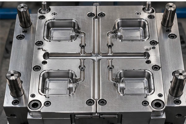
Injection mold runner pressure drop is a common issue that affects cavity filling and part quality. It occurs when molten plastic loses pressure as it flows through the runner system. Excessive pressure loss can cause short shots, uneven filling, and unstable production.
Several factors affect injection mold runner pressure drop, including runner diameter, flow length, material viscosity, and melt temperature. When pressure loss becomes too high, the injection machine may struggle to fill the mold cavities.
At Fentor Mold, we consider injection mold runner pressure drop during mold design. By optimizing runner geometry, balancing flow paths, and using mold flow analysis, engineers can reduce pressure loss and improve part quality.
This guide explains the main causes of runner pressure drop, how to calculate it, and practical ways to reduce it.
What Is Injection Mold Runner Pressure Drop?
Injection mold runner pressure drop is the difference in melt pressure between two points in a mold runner.
As molten plastic moves through the runner, it meets flow resistance. This resistance comes from material viscosity and runner geometry. As a result, pressure decreases along the flow path.
For example, consider these conditions:
- Runner inlet pressure: 100 MPa
- Runner outlet pressure: 75 MPa
- Runner pressure drop: 25 MPa
In this example, the plastic loses 25 MPa while passing through the runner.
The injection machine must provide enough pressure to overcome this loss. It must also supply the pressure needed to fill and pack the cavities.
Some pressure loss is unavoidable. However, excessive runner pressure drop can make the molding process harder to control.
A good runner design should support smooth melt flow while keeping material waste and production costs under control.
What Causes Injection Mold Runner Pressure Drop?
Several factors affect injection mold runner pressure drop. Most are related to runner geometry, material properties, and processing conditions.
Understanding these causes helps engineers choose the right solution.
How Runner Diameter Affects Injection Mold Runner Pressure Drop
Runner diameter has a major effect on pressure loss.
When a runner is too narrow, molten plastic faces greater flow resistance. As a result, the injection machine needs more pressure to move the material forward.
An undersized runner may cause:
- High injection pressure
- Excessive shear rates
- Uneven cavity filling
- Short shots
- Unstable molding conditions
Increasing runner diameter generally reduces flow resistance.
However, a larger cold runner uses more plastic and may take longer to cool.
Therefore, engineers should balance runner diameter, pressure loss, material waste, and cycle time.
How Runner Length Affects Injection Mold Runner Pressure Drop
Long runners create more pressure loss because the melt must travel a greater distance.
This problem often appears in large injection molds and multi-cavity tools.
For example, a 200 mm runner will generally cause more pressure loss than a 100 mm runner when other flow conditions remain the same.
However, runner length is not the only factor. Diameter, material viscosity, and flow rate also affect the result.
To improve the design, engineers can shorten runner branches and place cavities closer to the sprue.
A compact runner layout often reduces both pressure loss and material consumption.
Poor Runner Cross-Section
Runner shape affects flow resistance and heat loss.
Common runner cross-sections include:
- Full-round runners
- Trapezoidal runners
- Modified trapezoidal runners
- Half-round runners
- Rectangular runners
Full-round runners provide a large flow area relative to their perimeter. This helps reduce heat loss and flow resistance.
However, they require machining in both mold halves.
Trapezoidal runners are easier to manufacture in some mold designs. They can also provide good flow performance when sized correctly.
The best choice depends on the mold structure, plastic material, and production requirements.
How Material Viscosity Affects Injection Mold Runner Pressure Drop
Different plastics have different flow properties.
A high-viscosity material generally needs more pressure to pass through a runner.
Material viscosity depends on:
- Plastic type and grade
- Melt temperature
- Shear rate
- Material additives
- Material condition
For example, two grades of polypropylene may behave differently in the same mold.
A high-flow grade may require less filling pressure than a low-flow grade under similar conditions.
Therefore, engineers should use the actual material grade when evaluating runner pressure drop.
Material data sheets and mold flow analysis can provide useful information about melt viscosity.
Low Melt or Mold Temperature
Temperature strongly affects melt viscosity.
When melt temperature is too low, many thermoplastics become harder to flow. As a result, runner pressure drop increases.
In cold-runner molds, low mold temperature can also cause the frozen layer along the runner walls to grow faster.
This reduces the available flow area.
However, increasing temperature too much can create other problems. Excessive heat may cause material degradation, longer cooling cycles, or dimensional changes.
Therefore, engineers should follow the material supplier’s recommended processing range.
Sudden Runner Transitions
Abrupt changes in runner size or direction can create additional resistance.
For example, a large runner that suddenly connects to a narrow channel creates a local restriction.
Sharp corners and poor alignment may also affect melt flow.
To reduce these problems:
- Use smooth runner transitions.
- Avoid unnecessary narrow sections.
- Reduce sharp changes in direction.
- Check runner intersections.
- Remove machining steps and mismatched surfaces.
These changes can improve flow stability and reduce local pressure loss.
How Injection Mold Runner Pressure Drop Affects Part Quality
Excessive injection mold runner pressure drop can affect both filling and packing.
When too much pressure is lost inside the runner, less pressure remains available at the gate.
As a result, molded parts may develop quality problems.
| Molding Problem | Possible Effect of High Runner Pressure Drop |
|---|---|
| Short shots | Insufficient pressure reaches the cavity |
| Uneven filling | Different cavities receive different pressure levels |
| Sink marks | Lower packing pressure may increase local shrinkage |
| Dimensional variation | Inconsistent filling and packing conditions |
| Flash | Increased machine pressure may contribute to flash in some areas |
| Material degradation | Narrow runner sections may create excessive shear heating |
| Unstable production | Small processing changes may affect filling consistency |
However, these problems do not always come from runner pressure loss.
For example, short shots can also result from poor venting or insufficient shot volume. Similarly, sink marks may come from thick walls or poor cooling.
Therefore, engineers should evaluate the complete molding process before changing the runner.
How to Calculate Injection Mold Runner Pressure Drop
Injection mold runner pressure drop can be estimated using flow equations or mold flow simulation software.
The basic relationship is:
Runner Pressure Drop = Runner Inlet Pressure − Runner Outlet Pressure
Consider the following example:
| Parameter | Value |
|---|---|
| Runner inlet pressure | 110 MPa |
| Runner outlet pressure | 85 MPa |
| Runner pressure drop | 25 MPa |
| Pressure loss percentage | 22.7% |
In this example, the runner loses 25 MPa.
The pressure loss equals approximately 22.7% of the inlet pressure.
However, this percentage alone does not show whether the runner design is acceptable.
Engineers must also consider the pressure available at the gate, cavity filling requirements, and machine capacity.
Injection Mold Runner Pressure Drop Formula
For steady laminar flow of a Newtonian fluid through a circular channel, the Hagen–Poiseuille equation is:
ΔP = 8μLQ / (πr⁴)
Where:
- ΔP: Pressure drop (Pa)
- μ: Dynamic viscosity (Pa·s)
- L: Runner length (m)
- Q: Volumetric flow rate (m³/s)
- r: Runner radius (m)
This equation shows why runner diameter is important.
For a Newtonian fluid at a fixed flow rate, pressure drop is inversely proportional to the fourth power of the runner radius.
Therefore, a small increase in runner diameter can greatly reduce pressure loss.
However, molten thermoplastics are usually non-Newtonian. Their viscosity changes with temperature and shear rate.
As a result, this equation is only a simplified example.
For actual injection mold design, material-specific calculations and mold flow analysis provide more reliable results.
How to Reduce Injection Mold Runner Pressure Drop
Reducing injection mold runner pressure drop starts with identifying the main sources of flow resistance. Runner diameter, runner length, and gate design are often the first areas to check.
A well-designed runner system reduces unnecessary pressure loss while maintaining stable cavity filling and reasonable production costs.
The following methods can improve melt flow and reduce pressure loss.
1. Optimize Runner Diameter
Increasing runner diameter is one of the most direct ways to reduce pressure loss.
A larger flow channel gives molten plastic more space to move.
However, increasing every runner diameter is not always necessary.
Oversized cold runners can cause:
- Higher material consumption
- More runner waste
- Longer cooling time
- Higher production costs
Instead, engineers should identify the runner sections with the greatest pressure loss.
They can then increase the diameter where it provides a clear benefit.
This improves filling performance without adding unnecessary runner volume.
For more information, read our guide to Cold Runner Design for Injection Molding.
2. Reduce Runner Length
Shorter runners generally create less pressure loss.
Therefore, reducing runner length can improve filling without increasing the diameter.
Possible improvements include:
- Moving cavities closer to the sprue
- Simplifying runner branches
- Removing unnecessary runner extensions
- Improving cavity arrangement
- Reducing avoidable flow paths
However, the runner layout must also support cooling, ejection, mold strength, and part removal.
The shortest runner is not always the best design.
Engineers should balance flow performance with the overall mold structure.
3. Improve Runner Transitions
Smooth transitions help reduce unnecessary restrictions.
For example, a gradual change in runner diameter is generally better than a sudden reduction.
Rounded runner intersections can also improve flow stability.
In addition, engineers should check runner surfaces after machining.
A mismatch between mold halves can create an unexpected restriction.
Even when the CAD design is correct, poor machining or alignment may increase pressure loss.
Therefore, both design and manufacturing accuracy are important.
4. Balance the Runner System
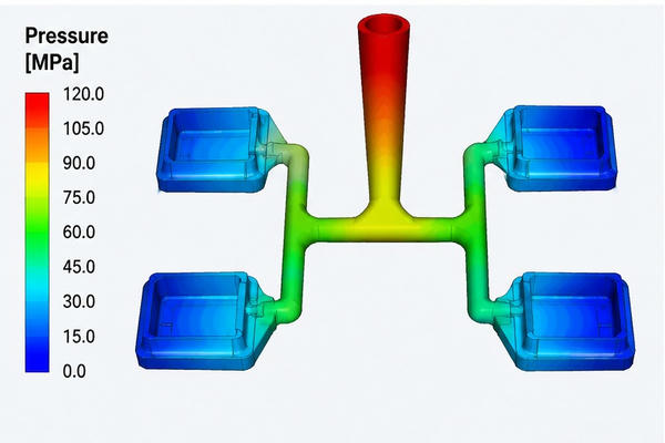
Runner balance is especially important in multi-cavity injection molds.
If one cavity receives melt earlier than another, the parts may fill at different rates.
This can lead to variations in part weight, dimensions, and appearance.
To improve runner balance, engineers can adjust:
- Runner branch lengths
- Runner diameters
- Gate dimensions
- Cavity arrangements
- Local flow restrictions
A balanced runner system should support consistent filling across all cavities.
However, identical runner dimensions do not always produce balanced filling.
Material behavior, cavity geometry, and shear heating can also affect flow.
Therefore, engineers should evaluate both runner geometry and actual filling performance.
Learn more in our article on Injection Mold Filling Balance: Runner and Gate Design.
5. Optimize Gate Size and Location
Runner pressure drop and gate pressure drop are different.
However, both affect the pressure available inside the cavity.
Even if the runner design is good, a small gate can create a major restriction.
Therefore, engineers should review gate size and location when investigating high filling pressure.
Important factors include:
- Gate cross-sectional area
- Gate length
- Gate location
- Melt flow direction
- Gate freeze time
- Part appearance requirements
A larger gate may reduce pressure loss. However, it can also create larger gate marks or affect packing performance.
The gate should support both filling efficiency and product quality.
Read our Injection Mold Gate Size Calculation Guide for more information.
6. Adjust Processing Conditions
Some runner pressure drop problems can be improved by adjusting processing settings.
However, process changes should stay within the material’s recommended limits.
Melt Temperature
Increasing melt temperature can reduce viscosity and improve flow.
However, excessive heat may degrade the material.
Injection Speed
Injection speed changes the melt flow rate and shear conditions.
A higher speed can reduce apparent viscosity in shear-thinning plastics. However, it also increases flow rate and may increase pressure demand.
Therefore, the result depends on the material and runner geometry.
Mold Temperature
A suitable mold temperature helps control cooling and premature freezing.
In cold-runner molds, this can affect the available melt flow area.
However, increasing mold temperature may also extend cooling time.
For these reasons, engineers should test process changes carefully.
Use Mold Flow Analysis to Reduce Injection Mold Runner Pressure Drop
Mold flow analysis is one of the most useful tools for evaluating injection mold runner pressure drop before manufacturing.
Simulation software can predict melt flow through the sprue, runners, gates, and cavities.
Engineers can review:
- Pressure distribution
- Maximum injection pressure
- Runner pressure loss
- Filling time
- Melt temperature
- Shear rate
- Cavity filling balance
For example, simulation may show that one runner branch creates much higher pressure loss than the others.
The engineer can then increase its diameter or modify the runner layout.
Afterward, the updated design can be simulated again.
This process helps compare different runner designs before steel cutting.
As a result, manufacturers can reduce the risk of costly mold modifications.
How to Identify Excessive Injection Mold Runner Pressure Drop
Before changing the mold, engineers should confirm where the pressure loss occurs.
The following steps provide a practical inspection process.
Step 1: Check the Filling Pattern
Start with short-shot trials.
These tests show how molten plastic fills the cavities.
If some cavities fill much earlier than others, the runner system may be unbalanced.
However, gate design, venting, and cavity geometry may also affect filling.
Therefore, the results should be reviewed together with other process data.
Step 2: Check Injection Pressure
Review the pressure required to fill the mold.
If the machine approaches its pressure limit before filling is complete, the flow path may have excessive resistance.
However, high machine pressure does not automatically mean the runner is responsible.
The restriction may be inside the nozzle, sprue, gate, or cavity.
Also, machine hydraulic pressure and plastic pressure are not always the same.
Engineers should use the correct pressure values when comparing results.
Step 3: Review Runner Geometry
Check the actual runner dimensions and compare them with the mold drawings.
Look for:
- Narrow runner sections
- Excessive runner length
- Sharp transitions
- Poorly aligned runner halves
- Blocked runner sections
- Machining defects
- Unexpected restrictions
Small geometric errors can create additional pressure loss.
Therefore, inspection is an important part of troubleshooting.
Step 4: Compare Mold Flow Results
Use mold flow analysis to identify areas with large pressure differences.
Compare pressure values at the runner inlet and outlet.
Also, review pressure changes across individual runner branches.
When comparing different designs, keep the material and filling conditions consistent.
This helps engineers understand whether the improvement comes from geometry or processing changes.
Step 5: Confirm the Improvement
After making changes, run new molding trials.
Check the following results:
- Complete cavity filling
- Stable injection pressure
- Consistent part weight
- Acceptable packing performance
- Suitable cycle time
- Stable dimensions
- Repeatable production quality
A successful improvement should reduce pressure loss without creating new molding defects.
Injection Mold Runner Pressure Drop in Cold and Hot Runners
Both cold-runner and hot-runner systems experience pressure loss.
However, their temperature conditions and flow behavior are different.
| Factor | Cold Runner | Hot Runner |
|---|---|---|
| Temperature control | Melt cools against mold steel | Heated manifold and nozzles |
| Frozen layer | Develops during filling | Generally avoided in heated channels |
| Pressure loss | May increase as the molten flow area becomes smaller | Depends on channel design and melt conditions |
| Material waste | Runner scrap is produced | Usually less runner waste |
| Main design factors | Runner size, cooling, and filling balance | Manifold size, nozzle design, and thermal balance |
| Main challenge | Balance pressure loss with waste and cycle time | Maintain suitable melt temperature and flow balance |
Cold Runner Pressure Drop
In a cold-runner mold, the runner is not continuously heated.
As molten plastic contacts the cooler mold walls, a frozen layer begins to form.
This reduces the effective flow area.
Therefore, pressure loss can increase during filling, especially when the runner is narrow or the melt temperature is low.
Hot Runner Pressure Drop
A hot-runner system keeps plastic molten inside heated channels.
This helps avoid the frozen layer found in cold runners.
However, hot runners can still create significant pressure loss.
Long manifold channels, narrow nozzles, and restrictive gates may increase resistance.
As a result, proper channel sizing and temperature control remain important.
For more information, see our Hot Runner System Injection Molding Design Guide.
Common Injection Mold Runner Pressure Drop Mistakes
Some changes can reduce runner pressure drop but create new molding problems.
Avoiding these mistakes helps engineers improve the complete process.
Making Every Runner Larger
Increasing runner diameter can lower flow resistance.
However, oversized cold runners use more material and may increase cooling time.
Therefore, runner dimensions should be optimized rather than simply enlarged.
Increasing Injection Pressure Without Checking the Runner
Higher injection pressure may improve filling temporarily.
However, it does not remove the restriction inside a poorly designed runner.
It may also increase machine loads or contribute to flash.
The better approach is to identify the actual cause of high pressure loss.
Ignoring Gate Restrictions
A runner may have acceptable pressure loss while the gate remains too small.
As a result, the machine may still need high injection pressure.
Therefore, engineers should evaluate the complete flow path from the nozzle to the cavity.
Using the Same Runner Size for Every Material
Different plastics have different flow properties.
For example, a runner designed for a high-flow polypropylene grade may not work well with a more viscous engineering plastic.
Therefore, runner sizing should consider the actual material grade.
Relying Only on Simulation
Mold flow analysis provides valuable predictions.
However, actual production conditions may differ from the simulation.
Material variation, mold temperature, machining accuracy, and machine settings can affect filling.
Therefore, engineers should verify the design through mold trials.
How Fentor Mold Reduces Injection Mold Runner Pressure Drop
At Fentor Mold, we understand how injection mold runner pressure drop affects filling performance, part quality, and production efficiency.
During mold development, our engineers review runner geometry, gate design, and material flow behavior to reduce unnecessary pressure loss.
Our goal is to support stable cavity filling, consistent product quality, and efficient production.
Runner Design
We review runner diameter, length, layout, and transitions to reduce unnecessary flow resistance.
Gate Design
We evaluate gate dimensions and locations based on part geometry, material properties, and filling requirements.
Cavity Filling Balance
For multi-cavity molds, we consider how the runner layout affects the filling of each cavity.
Mold Flow Analysis
When required, mold flow analysis helps us evaluate pressure distribution and identify possible filling problems before tooling begins.
Mold Trials
During mold testing, we review filling behavior, part quality, and processing conditions to confirm mold performance.
These steps are especially useful for automotive plastic components, multi-cavity molds, and precision injection molded parts.
By considering runner pressure drop early, manufacturers can reduce the risk of later mold changes and improve production stability.
Frequently Asked Questions
What Is an Acceptable Runner Pressure Drop?
There is no universal acceptable runner pressure drop for every injection mold.
The correct value depends on the plastic material, runner geometry, filling speed, machine capacity, and cavity pressure requirements.
The most important factor is whether enough pressure remains available for stable filling and packing.
Does Increasing Runner Diameter Reduce Pressure Drop?
Yes. Increasing runner diameter generally reduces flow resistance.
However, larger cold runners also increase material waste and may extend cooling time.
Therefore, the best runner diameter should balance pressure loss and production efficiency.
Does Melt Temperature Affect Runner Pressure Drop?
Yes. Melt temperature affects plastic viscosity.
For most thermoplastics, a higher melt temperature reduces viscosity and can lower pressure loss under comparable flow conditions.
However, the temperature must remain within the material supplier’s recommended range.
Can Runner Pressure Drop Cause Short Shots?
Yes. Excessive pressure loss can reduce the pressure available to fill the cavity.
If the machine cannot provide enough pressure, the melt may stop before filling is complete.
However, short shots can also result from poor venting, restrictive gates, or insufficient material.
How Does Runner Length Affect Pressure Drop?
Longer runners generally create greater pressure loss when other flow conditions remain the same.
Therefore, shortening the runner can improve filling efficiency.
However, the runner layout must also support mold strength, cooling, and ejection.
Can Mold Flow Analysis Reduce Runner Pressure Drop?
Mold flow analysis helps engineers identify high-pressure-loss areas and compare runner designs.
By reviewing pressure distribution, flow behavior, and cavity filling balance, engineers can optimize runner geometry before manufacturing the mold.
Conclusion
Injection mold runner pressure drop affects cavity filling, injection pressure, and production stability.
The main causes include narrow runners, long flow paths, high material viscosity, poor transitions, and unsuitable processing conditions.
To reduce runner pressure drop, engineers should optimize runner diameter, shorten unnecessary flow paths, improve runner balance, and review gate design.
Mold flow analysis can also help identify restrictions before mold manufacturing begins.
At Fentor Mold, we focus on practical injection mold design solutions that support stable filling, consistent part quality, and efficient production.
Need support with runner design or a new injection mold project? Contact Fentor Mold to discuss your tooling requirements.