
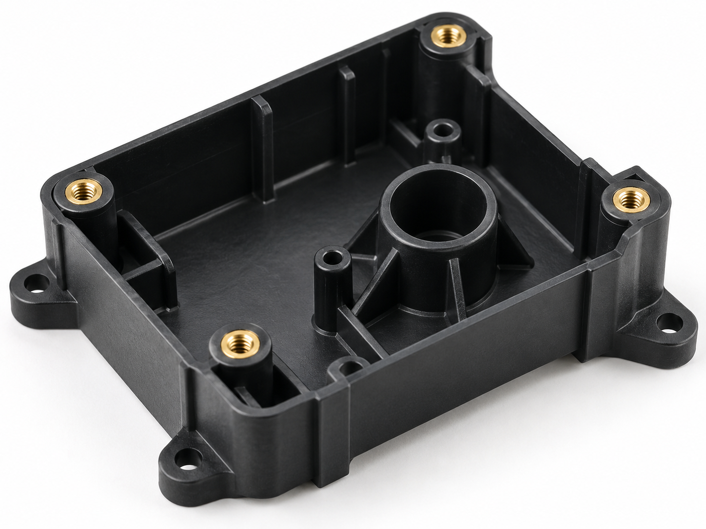
Metal insert injection molding is widely used when a plastic part needs threaded inserts, bushings, pins, electrical contacts, shafts, or other metal components molded directly into the part.
The process looks simple. The operator or automation system places the metal insert into the mold, the mold closes, and plastic flows around it.
However, keeping the insert in the correct position is often much more difficult than it appears.
A small insert movement during molding can cause:
- Hole position errors
- Incorrect thread position
- Uneven plastic wall thickness
- Assembly problems
- Insert exposure
- Poor sealing
- Weak mechanical strength
For plastic parts with tight assembly requirements, insert position accuracy must therefore be considered from the beginning of the mold design.
At FENTOR MOLD, we normally review the insert tolerance, locating structure, plastic flow direction, injection pressure, and final inspection requirements together before mold manufacturing starts.
Why Does Insert Position Accuracy Matter?
Many metal inserts perform a functional role rather than simply being embedded inside the plastic.
For example, an insert may need to align with:
- A screw
- Another housing
- A PCB
- A mating shaft
- A connector
- A sealing surface
If the metal insert moves even slightly, the final plastic part may still look normal but fail during assembly.
This is especially important when several inserts must maintain their relative positions.
For example, a housing may contain four threaded brass inserts. Each individual insert may be within tolerance, but if their pitch positions vary too much, the mating metal plate may no longer assemble correctly.
Therefore, metal insert injection molding accuracy should be evaluated according to the final assembly requirement, not only by checking whether the insert remains inside the plastic.
What Causes Metal Inserts to Move During Injection Molding?
Insert movement usually comes from several factors working together.
The most common causes include:
- Poor insert positioning
- Excessive clearance between insert and locating pin
- High injection pressure
- Plastic flow directly hitting the insert
- Uneven filling around the insert
- Insert dimensional variation
- Mold component wear
- Incorrect manual loading
- Insert deformation during mold closing
Finding the real cause is important because simply reducing injection pressure does not always solve the problem.
1. Improve the Metal Insert Locating Structure
The first step is to make sure the insert has a stable reference inside the mold.
The insert should not rely only on friction to stay in place.
Depending on the part design, common positioning methods include:
- Locating pins
- Core pins
- Shoulder positioning
- Step positioning
- Insert pockets
- Spring-loaded locating components
A good locating design should control both the insert position and its orientation.
For example, if a threaded brass insert sits on a cylindrical pin, the pin diameter and insert internal diameter determine radial movement.
If the clearance is too large, the insert may shift before injection even starts.
However, the fit also cannot be excessively tight. Otherwise, operators may have difficulty loading the insert, or the insert may become stuck on the pin after molding.
The correct solution is a controlled production tolerance rather than simply making the fit as tight as possible.
For more complex tooling, the locating structure should be reviewed during the early injection mold design stage.
2. Control Insert Tolerance Before Designing the Mold
One common mistake is designing the mold based only on the nominal insert dimension.
Metal inserts also have manufacturing tolerances.
For example, a brass threaded insert may vary in:
- Outer diameter
- Inner diameter
- Length
- Knurl diameter
- Flange thickness
- Concentricity
If the mold locating pin is designed according to one sample instead of the insert drawing and tolerance range, problems may appear during mass production.
Some insert batches may fit tightly, while others may be loose.
Therefore, before finalizing the mold design, confirm:
- The insert drawing
- Critical insert tolerances
- Supplier capability
- Whether the insert supplier may change
- Whether plating or secondary treatment changes the dimensions
This step is particularly important for high-volume metal insert injection molding projects.
3. Avoid Plastic Flow Directly Hitting the Insert
Even when the insert is positioned correctly before injection, molten plastic can still push it out of position.
During filling, plastic enters the cavity at high speed and pressure.
If the main flow front directly impacts one side of the metal insert, it can create a strong lateral force.
This may cause:
- Insert tilting
- Side movement
- Bending of a long insert
- Deformation of a locating pin
For this reason, gate position can strongly affect insert position accuracy.
Whenever possible, the plastic should flow around the insert in a balanced way instead of striking it from one direction.
For complicated parts, Moldflow analysis can help engineers understand how the plastic reaches the insert before the mold is built.
At FENTOR MOLD, gate position is normally reviewed together with the insert locating method because a strong locating pin alone may not prevent movement if the melt flow continuously pushes the insert from one side.
4. Reduce Unnecessary Injection Pressure
High injection pressure increases the force acting on the metal insert.
However, reducing pressure blindly is not the right solution.
If pressure becomes too low, the part may develop:
- Short shots
- Poor packing
- Weld lines
- Sink marks
- Incomplete filling
Instead, engineers should first look for the reason the pressure is high.
Possible causes include:
- Gate too small
- Runner too thin
- Poor gate location
- Thin plastic sections
- Low mold temperature
- Low material temperature
- Long flow distance
Improving the filling system can often reduce the load on the insert without sacrificing part quality.
This is one reason mold design and injection molding production should be considered together.
Metal Insert Injection Molding Needs Strong Locating Pins
The locating pin is often one of the most important mold components in an insert molding tool.
If the locating pin is too thin or too long, injection pressure can cause it to deflect.
Even a small deflection may change the final insert position.
Therefore, engineers should check:
- Pin diameter
- Unsupported pin length
- Steel grade
- Heat treatment
- Insert weight
- Plastic pressure direction
Whenever possible, the locating pin should be short and well supported.
For long inserts or deep plastic parts, increasing only the pin hardness may not solve the problem. The pin geometry itself may need to change.
Support the Insert From Both Sides When Possible
Some insert designs allow the mold to support the metal component from both sides.
This can greatly improve stability.
For example, a long metal sleeve may be positioned between the core and cavity rather than being supported only from one end.
However, this method requires careful mold fitting.
If the mold closes directly onto the insert, engineers must consider:
- Insert length tolerance
- Mold closing force
- Risk of crushing the insert
- Parting-line flash
- Insert deformation
There must be enough control to hold the insert securely without damaging it.
Manual Insert Loading Can Also Create Position Errors
Not every insert position problem comes from the mold.
For lower production volumes, operators often load inserts manually.
If the insert can be installed at different depths or orientations, operator variation becomes another source of dimensional error.
A good manual loading design should make incorrect installation difficult.
Useful design features include:
- Positive stops
- Directional locating features
- Simple loading orientation
- Visible seating surfaces
- Poka-yoke features
The operator should be able to clearly feel or see when the insert has reached the correct position.
If loading requires repeated adjustment by hand, the process will usually become less stable during long production runs.
Check Whether the Insert Moves During Mold Closing
Sometimes the insert is correctly loaded but moves when the mold closes.
This can happen when:
- The insert contacts the opposite mold half too early
- The locating pin is not aligned correctly
- The insert sits at an angle
- The mold closing action pushes the insert sideways
- Insert length varies between batches
During mold trials, engineers should therefore inspect the insert position before and after mold closing whenever possible.
This helps separate loading problems from injection-pressure problems.
Shrinkage Can Make the Insert Look Misaligned
Not every position error is caused by the metal insert physically moving.
Plastic shrinkage can also change the measured relationship between the insert and the final plastic geometry.
For example, the metal insert may remain exactly where the mold positioned it, but the surrounding plastic may shrink or warp.
The final inspection may then show that the insert is off-center relative to:
- A plastic hole
- An outer wall
- A boss
- A mating surface
In this situation, changing the locating pin position may actually make the problem worse.
The engineer first needs to determine whether the error comes from:
- Insert displacement
- Plastic shrinkage
- Part warpage
- Mold machining error
This distinction is critical before making a mold correction.
Check Insert Position After the Part Fully Cools
Plastic parts can continue changing dimensions after ejection.
Therefore, critical insert positions should not always be judged immediately beside the molding machine.
For tight tolerance parts, dimensional inspection should follow a defined conditioning time.
The inspection method may include:
- CMM
- Vision measurement
- Height gauge
- Dedicated checking fixture
- Functional assembly gauge
The correct method depends on the tolerance and final application.
Multi-Cavity Molds Need Cavity-by-Cavity Control
Insert position problems become more difficult in multi-cavity molds.
Suppose an eight-cavity mold produces the same part.
The overall dimensional report may look acceptable, but one or two cavities may consistently produce inserts outside tolerance.
Possible causes include:
- Different locating pin clearances
- Uneven cavity filling
- Local mold temperature differences
- Individual component wear
- Different insert seating conditions
For this reason, parts should remain traceable by cavity during mold trials and early production.
Do not mix all samples together before dimensional inspection.
Cavity-by-cavity data makes troubleshooting much faster.
Insert Position Accuracy Can Change During Long Production Runs
A mold may produce good parts during the first trial but gradually lose accuracy after thousands of cycles.
Common causes include:
- Locating pin wear
- Insert pocket wear
- Repeated metal-to-metal contact
- Contamination
- Damaged spring components
- Operator loading damage
Metal inserts are usually harder than plastic. Therefore, they can gradually wear the mold components that locate them.
For high-volume production, replaceable locating components are often better than machining the locating feature directly into an expensive cavity insert.
This makes future maintenance easier and reduces repair cost.
What Should Be Checked During the Mold Trial?
During a metal insert injection molding trial, do not inspect only the appearance of the plastic part.
The team should also check:
- Insert X, Y, and Z position
- Insert angle
- Insert depth
- Thread condition
- Insert rotation
- Plastic coverage around the insert
- Flash near the metal interface
- Cracks around the insert
- Pull-out strength if required
- Cavity-to-cavity variation
It is also useful to compare the first shots with parts produced after the mold reaches a stable temperature.
A mold that produces one good sample does not automatically guarantee stable mass production.
You can also review our guide on injection mold trials for other checks that should be completed before production approval.
How FENTOR MOLD Controls Insert Position Accuracy
For insert molding projects, FENTOR MOLD normally reviews both the tooling and production conditions instead of treating insert displacement as a single molding parameter problem.
The process may include:
- Reviewing insert drawings and tolerances
- Checking the locating method
- Evaluating gate position
- Reviewing plastic flow direction
- Measuring critical mold components
- Checking insert position during mold trials
- Comparing different cavities
- Adjusting molding parameters when necessary
The goal is not simply to hold the insert firmly.
The goal is to maintain the required relationship between the metal insert and the finished plastic part throughout stable production.
Conclusion
Good metal insert injection molding depends on more than placing a metal component inside a mold.
Insert position accuracy is affected by the insert tolerance, locating structure, gate position, injection pressure, plastic shrinkage, operator loading, mold wear, and inspection method.
For tight-tolerance plastic parts, these factors should be considered before mold manufacturing begins.
A stable process usually comes from three things:
- Accurate insert positioning
- Controlled plastic flow
- Reliable dimensional verification
When these areas are handled correctly, plastic parts with metal inserts can maintain much better assembly accuracy and production consistency.
If you are developing a plastic part with threaded inserts, bushings, pins, contacts, or other metal components, FENTOR MOLD can support the project from mold design and manufacturing through injection molding production.