
PC injection molding is widely used for plastic parts that require high impact resistance, good dimensional stability, heat resistance, and long-term durability. Polycarbonate is commonly used for automotive components, electronic housings, appliance parts, industrial equipment, protective covers, and transparent plastic products.
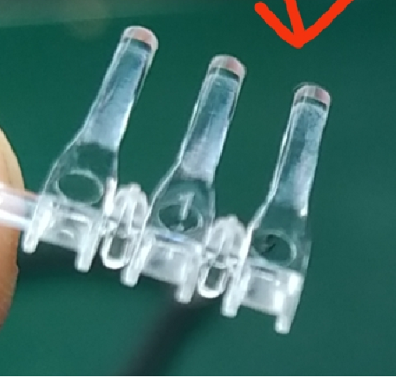
However, PC is more demanding to mold than many common thermoplastics. Moisture, wall thickness, gate location, cooling, venting, and processing conditions can all affect the final part.
A well-designed PC injection molded part therefore requires more than simply selecting the correct resin. The product design and injection mold should be considered together from the beginning.
This article explains the main PC material properties, practical part design rules, mold design considerations, common injection molding defects, and ways to improve production quality.
- PC provides excellent impact resistance, stiffness, heat resistance, and dimensional stability.
- PC resin must be properly dried before injection molding.
- Uniform wall thickness helps reduce sink marks, warpage, and internal stress.
- Ribs and bosses should be designed carefully to avoid excessive material thickness.
- Adequate draft is important for smooth ejection.
- Gate location affects filling, weld lines, appearance, and residual stress.
- Balanced mold cooling is essential for dimensional stability.
- Good venting helps prevent burn marks, short shots, and other filling problems.
- PC injection molding defects should be considered during part and mold design, not only during production.
What Is PC Injection Molding?
PC injection molding is a manufacturing process in which polycarbonate resin is heated until it becomes molten and then injected into a mold cavity under controlled pressure.
The basic process includes:
- Drying the PC resin.
- Feeding the material into the injection molding machine.
- Heating and plasticizing the resin.
- Injecting the molten PC into the mold.
- Applying holding pressure to compensate for material shrinkage.
- Cooling the part inside the mold.
- Opening the mold and ejecting the finished part.
Although the basic injection molding process is similar to other thermoplastics, PC requires careful control because the material is sensitive to moisture and processing conditions.
The mold itself also has a significant effect on the finished product. Runner design, gate position, cooling channels, vents, ejector locations, and cavity surface finish all need to be considered.
For projects where the product design still needs validation before production tooling, Fentormold Prototype Injection Molding can be used to evaluate the part before committing to full-scale production.
PC Material Properties for Injection Molding
Polycarbonate is an engineering thermoplastic with a combination of mechanical and thermal properties that makes it suitable for demanding applications.
High Impact Resistance
High impact resistance is one of the main reasons manufacturers choose PC.
PC can withstand impacts better than many conventional plastics, making it suitable for protective covers, housings, automotive components, and industrial parts.
However, material strength alone does not guarantee a strong molded component.
Sharp internal corners, abrupt wall transitions, thin sections, and excessive molded-in stress can still create weak areas. Therefore, part geometry must be considered together with the material.
Good Strength and Stiffness
PC provides good rigidity while maintaining relatively low weight.
Instead of making an entire part thicker, designers can often use ribs, gussets, and properly positioned support structures to improve stiffness.
This approach can reduce material consumption while also improving cooling and reducing the risk of sink marks.
Heat Resistance
Compared with many commodity plastics, PC offers good heat resistance.
This makes it useful for applications involving elevated operating temperatures, such as:
- Automotive components
- Electrical housings
- Electronic products
- Appliance components
- Industrial equipment
The actual temperature performance depends on the specific PC grade and application conditions, so the resin manufacturer’s technical data should always be checked before material selection.
Dimensional Stability
PC can provide good dimensional stability when the part is properly designed and processed.
However, dimensional accuracy is affected by several factors, including:
- Mold temperature
- Cooling balance
- Part geometry
- Gate position
- Processing conditions
- Material grade
- Mold construction
For precision components, material selection and mold design should therefore be evaluated together.
Transparency
Certain PC grades provide excellent transparency.
Transparent PC is commonly used for:
- Protective covers
- Lighting components
- Transparent housings
- Optical components
- Safety windows
For transparent products, mold surface quality becomes especially important. Small scratches, contamination, weld lines, flow marks, or gas marks can become highly visible.
PC Injection Molding Design Rules
A large percentage of injection molding problems can be reduced during the product design stage.
Good PC injection molding design should consider wall thickness, draft, ribs, bosses, corners, undercuts, and the overall flow path.
1. Keep Wall Thickness as Uniform as Possible
Uniform wall thickness is one of the most important principles in PC part design.
Large changes in wall thickness can cause different areas of the part to cool and shrink at different rates. This can result in:
- Sink marks
- Warpage
- Internal stress
- Voids
- Dimensional variation
If a thick section is required for strength, consider coring out the area instead of creating a large solid block.
This is especially important around bosses, mounting points, and structural features.
2. Avoid Excessively Thick Ribs
Ribs are useful for improving stiffness without increasing the overall wall thickness.
However, an overly thick rib can create a localized thick section. During cooling, this area may shrink differently from the surrounding wall and produce sink marks.
As a general design approach, ribs should be thinner than the nominal wall and should provide stiffness through geometry rather than simply adding material.
The exact rib thickness should be determined according to the part’s structure, appearance requirements, PC grade, and molding conditions.
3. Design Bosses Carefully
Bosses are commonly used for:
- Screws
- Inserts
- Locating pins
- Assembly features
- Fasteners
A common mistake is making the boss completely solid.
A better approach is often to core out the boss and use ribs to connect it to the surrounding structure. This reduces the amount of material concentrated in one location and can lower the risk of sink marks.
The connection between the boss and the main wall should also be designed with appropriate radii and support.
4. Add Adequate Draft
Draft allows the molded part to separate from the mold more easily.
Without sufficient draft, the part can drag against the cavity or core surface during ejection.
This may cause:
- Scratches
- Drag marks
- Deformation
- Ejector marks
- Difficult ejection
The required draft depends on the wall depth, surface texture, mold finish, and part geometry.
Textured surfaces generally require more draft than smooth surfaces.
Draft should be considered before mold design begins rather than added after the mold has already been manufactured.
5. Use Rounded Internal Corners
Sharp corners can concentrate stress and interfere with smooth material flow.
Adding suitable radii can:
- Reduce stress concentration
- Improve melt flow
- Improve part strength
- Reduce machining difficulty
- Improve mold life
For PC parts subjected to impact or mechanical loading, rounded transitions are particularly useful.
PC Mold Design Considerations
Good PC injection molding requires a mold designed around both the material and the part geometry.
For precision tooling, the mold structure, machining accuracy, cooling system, and mold components all contribute to final part quality.
Gate Location
Gate location affects how molten PC flows through the cavity.
A poorly positioned gate can cause:
- Excessive filling pressure
- Long flow lengths
- Weld lines in critical areas
- Uneven packing
- Appearance problems
- Residual stress
The gate should therefore be selected based on the wall thickness, flow direction, cosmetic requirements, and functional areas of the part.
For complex components, gate location should ideally be reviewed during the DFM stage.
Runner Design
The runner system must provide stable material flow from the injection machine to the cavity.
The design should consider:
- Number of cavities
- Flow balance
- Runner dimensions
- Gate type
- Pressure loss
- Material consumption
For multi-cavity molds, balanced filling is especially important.
Mold Venting
When molten PC enters the cavity, the air already inside the mold must escape.
Poor venting can lead to:
- Burn marks
- Short shots
- Gas marks
- Weld line problems
- Poor surface appearance
Vents should be positioned according to the expected flow path and end-of-fill locations.
Deep ribs, blind pockets, and thin sections deserve particular attention.
Cooling System
Cooling has a major effect on PC part quality.
If different areas of the mold cool at significantly different rates, the molded part may experience uneven shrinkage.
This can result in:
- Warpage
- Dimensional variation
- Residual stress
- Uneven appearance
Cooling channels should therefore be designed according to the actual part geometry rather than simply using a standard layout.
For customers requiring precision mold components, Fentormold Components Manufacturing provides a relevant manufacturing capability for precision mold components used in injection tooling.
Common PC Injection Molding Defects
Even with a well-designed mold, processing defects can occur. The key is to identify the underlying cause instead of simply changing machine parameters.
Sink Marks
Sink marks appear as small depressions on the molded surface.
Common causes include:
- Thick walls
- Thick ribs
- Thick bosses
- Insufficient packing
- Poor cooling
- Excessive local material accumulation
The best solution is often to address the part design first.
Reducing unnecessary thickness and coring out heavy sections can be more effective than simply increasing holding pressure.
Warpage
Warpage occurs when different areas of a part shrink unevenly.
Typical causes include:
- Uneven wall thickness
- Unbalanced cooling
- Poor gate position
- Residual stress
- Improper processing conditions
A balanced cooling system and uniform part geometry are important for reducing warpage.
For more information about controlling deformation after molding, see Fentormold’s related article on How to Prevent Injection Molding Warpage After Cooling.
Short Shots
A short shot occurs when the molten plastic does not completely fill the cavity.
Possible causes include:
- Insufficient injection pressure
- Long flow paths
- Thin walls
- Poor gate design
- Low melt temperature
- Insufficient venting
Before simply increasing injection pressure, engineers should determine whether the part geometry and mold flow system are suitable for PC.
Weld Lines
Weld lines occur when two or more flow fronts meet.
They can be especially noticeable on cosmetic PC components.
Weld lines can also become weaker areas depending on the material, processing conditions, and geometry.
Gate location, flow direction, venting, and wall thickness should therefore be considered together.
Burn Marks
Burn marks are often related to trapped air or gas.
When air becomes compressed in an area where the melt front reaches the end of the cavity, the temperature can rise sharply and cause a dark or burned appearance.
Common locations include:
- End-of-fill areas
- Deep ribs
- Blind pockets
- Poorly vented sections
Improving venting and optimizing filling conditions can help reduce this problem.
Silver Streaks
Silver streaks or moisture-related streaks can appear when moisture remains in the PC resin.
PC should be dried according to the resin supplier’s recommended drying conditions before molding.
Proper material storage is also important. Even properly dried resin can absorb moisture again if it is exposed to humid air for an extended period.
How to Improve PC Injection Molding Quality
A reliable PC molding project should be managed from product design through mold manufacturing and production.
Step 1: Confirm the PC Grade
Do not specify the material simply as “PC” for a demanding application.
The project should confirm the required:
- PC grade
- Impact performance
- Heat resistance
- Flame retardancy
- UV resistance
- Transparency
- Color
- Regulatory requirements
Different PC grades can have significantly different molding and performance characteristics.
Step 2: Perform a DFM Review
Before mold manufacturing begins, review:
- Wall thickness
- Draft angles
- Ribs
- Bosses
- Undercuts
- Parting line
- Gate location
- Ejection
- Cosmetic surfaces
Early DFM review can identify problems before they become expensive mold modifications.
Fentormold’s Injection Mold Manufacturing service can support projects from mold design through tooling production.
Step 3: Consider Mold Flow
For complex PC components, mold-flow analysis can help evaluate:
- Filling behavior
- Pressure requirements
- Weld line locations
- Air traps
- Cooling
- Potential warpage
This is particularly useful for large housings, thin-wall components, multi-cavity molds, and appearance-critical parts.
Step 4: Validate With Trial Molding
After mold completion, trial molding should verify:
- Part dimensions
- Surface appearance
- Filling balance
- Ejection
- Warpage
- Sink marks
- Weld lines
- Cycle stability
The goal is not simply to produce one acceptable sample. The objective is to establish a stable molding process that can repeatedly produce qualified parts.
PC Injection Molding Applications
PC is suitable for many industries because it combines mechanical performance with good processing flexibility.
Typical applications include:
Automotive
- Interior components
- Protective covers
- Electronic housings
- Lighting-related components
- Structural plastic parts
Electronics
- Electronic housings
- Connectors
- Protective covers
- Electrical components
Home Appliances
- Control housings
- Transparent covers
- Structural components
- Functional internal parts
Industrial Equipment
- Protective guards
- Equipment housings
- Machine components
- Safety covers
Consumer Products
- Protective cases
- Transparent components
- Durable housings
- Functional plastic components
When a product moves from prototype to volume production, the mold strategy should also change accordingly. Fentormold Injection Molding Production can support production-stage injection molding after tooling validation.
PC Injection Molding vs. Other Plastics
PC should not automatically be selected simply because it has high impact strength.
Material selection should consider the complete application.
| Property | PC | ABS | PA | PP |
|---|---|---|---|---|
| Impact resistance | Excellent | Good | Good–Excellent | Good |
| Stiffness | High | Medium–High | High | Medium |
| Heat resistance | High | Medium | High | Medium |
| Moisture sensitivity | Moderate | Low | High | Very Low |
| Chemical resistance | Moderate | Moderate | Good | Excellent |
| Transparency | Excellent in suitable grades | Limited | Limited | Limited |
| Typical applications | Automotive, electronics, protective parts | Housings, appliances | Mechanical parts | Consumer products |
For example, if a component needs high impact resistance and transparency, PC may be a strong candidate.
If chemical resistance or low material cost is the primary requirement, another material may be more appropriate.
Material selection should therefore be based on the actual operating environment, performance requirements, production volume, and cost target.
When Should You Choose PC Injection Molding?
PC is a good candidate when a molded plastic component requires a combination of:
- High impact resistance
- Good stiffness
- Heat resistance
- Dimensional stability
- Durability
- Transparency
- Electrical insulation
- High-quality appearance
However, PC is not the right choice for every plastic product.
The final material decision should consider:
Product requirements + operating environment + part design + production volume + cost target.
This approach helps avoid selecting a material based on only one performance characteristic.
Final Thoughts
PC injection molding is an effective manufacturing solution for demanding plastic components that require strength, impact resistance, heat resistance, and dimensional stability.
However, achieving consistent quality requires more than choosing a good PC resin.
The part should be designed for injection molding from the beginning. Uniform wall thickness, properly designed ribs and bosses, adequate draft, rounded corners, and appropriate gate locations can significantly reduce molding problems.
At the mold level, balanced cooling, effective venting, suitable runner and gate design, accurate mold components, and reliable ejection are equally important.
Common defects such as sink marks, warpage, short shots, weld lines, burn marks, and silver streaks should be considered during the DFM and mold design stages rather than being treated only as production problems.
For companies developing PC components for automotive, electronics, appliances, and industrial applications, early cooperation between the product designer, injection molding engineer, and mold manufacturer can help identify potential problems before they result in costly tooling changes.