
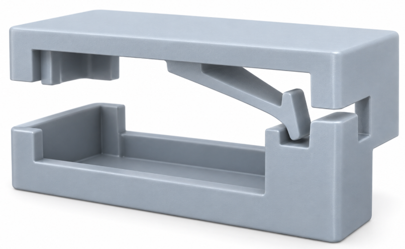
A good snap fit design should allow plastic parts to assemble easily, lock securely, and avoid cracking during use.
Snap fits are widely used because they remove screws, inserts, and other secondary fasteners. However, the design must balance flexibility, retention force, material behavior, and moldability.
For injection molded parts, small changes in beam thickness, hook size, root radius, or clearance can have a large effect on performance.
What Is a Snap Fit?
A snap fit is an integrated fastening feature molded directly into a plastic part.
During assembly, the flexible section bends temporarily. Once the hook passes the mating feature, it returns toward its original position and locks the parts together.
A typical snap fit includes:
- Flexible beam
- Beam root
- Hook
- Lead-in surface
- Retention surface
- Mating feature
- Clearance for deflection
The design must allow enough movement for assembly without pushing the plastic beyond a safe strain level.
Common Snap Fit Types
Cantilever Snap Fit
The cantilever snap fit is the most common design.
It uses a flexible beam fixed at one end and a hook at the other. During assembly, the beam bends until the hook passes the mating edge.
Important design factors include:
- Beam length
- Beam thickness
- Hook height
- Root radius
- Required deflection
- Assembly angle
A longer beam usually provides more flexibility and lower stress.
A short, thick beam is much stiffer and may require excessive assembly force.
U-Shaped Snap Fit
A U-shaped snap fit provides a longer flexible path when straight beam length is limited.
It can improve flexibility, but the geometry may increase mold complexity.
Annular Snap Fit
Annular snap fits are commonly used on round or cylindrical parts.
The circular feature expands or contracts during assembly.
Important factors include:
- Interference
- Wall thickness
- Material flexibility
- Engagement depth
Too much interference can create excessive assembly stress.
Material Selection for Snap Fit Design
Material selection is important because different plastics tolerate very different levels of deformation.
PP
Polypropylene is one of the most suitable materials for flexible snap fits.
Advantages include:
- Good ductility
- Good fatigue resistance
- High flexibility
- Low material cost
It works especially well when repeated assembly is required.
However, PP has relatively high shrinkage, so engagement dimensions need careful control.
PA
Nylon materials such as PA6 and PA66 offer good strength and toughness.
They can perform well in snap fit applications, especially where mechanical strength is important.
However, moisture absorption may affect part dimensions and stiffness.
ABS
ABS is often used in housings and consumer plastic parts.
It provides good toughness and appearance, but the snap arm should not be forced to bend excessively.
Smooth root geometry and controlled deflection are important.
PC and PC+ABS
PC and PC+ABS can also be used for snap fits where higher rigidity is required.
However, these materials are less forgiving than PP when the snap arm is short or highly stressed.
For rigid materials, increasing beam length is often better than increasing thickness.
Key Snap Fit Design Guidelines
Control Beam Thickness
The snap beam must be flexible enough to bend during assembly.
If the beam is too thick:
- Assembly force increases
- Root stress increases
- Cracking risk increases
If the beam is too thin:
- Retention may become weak
- Filling may become more difficult
- The feature may deform during ejection
The beam should be designed as part of the whole snap system rather than as an isolated feature.
Increase Beam Length Where Possible
A longer beam can normally provide the same deflection with lower stress.
This is one of the simplest ways to improve a snap fit.
When space allows, increasing beam length is often more effective than making the arm thicker.
Add a Smooth Root Radius
The beam root is a common failure area.
Sharp internal corners create stress concentration and may cause cracking during assembly.
A smooth radius helps distribute stress more evenly.
This is especially important for ABS, PC, and other relatively rigid materials.
Optimize Hook Geometry
The hook controls both assembly and retention.
The lead-in side should allow smooth assembly.
The retention side should provide enough locking force.
If the hook is too large, the snap arm must bend farther during assembly.
That increases stress and may make the part difficult to assemble.
A larger hook is not always a stronger design.
Leave Enough Deflection Clearance
The snap arm needs enough space to move during assembly.
Designers should check the arm in its maximum deflected position.
If the arm contacts another wall before the hook passes the mating feature, assembly may become impossible.
Clearance should also consider:
- Tolerances
- Mold shrinkage
- Part warpage
- Assembly variation
Snap Fit Tolerance and Engagement
Snap fits are very sensitive to dimensions.
If engagement is too small, the joint may feel loose.
If engagement is too large, the arm may require excessive deflection.
Important dimensions include:
- Hook height
- Beam position
- Mating edge position
- Final engagement
- Clearance between parts
These dimensions should be checked using tolerance limits rather than only nominal CAD values.
Material shrinkage must also be considered during mold design.
Mold Design Considerations
A snap fit may work well in CAD but still create problems during mold manufacturing.
The main issue is usually the hook undercut.
Before tooling starts, the mold engineer should check whether the snap fit can release in the normal mold opening direction.
Some snap features can release directly. Others may require:
- Sliders
- Lifters
- Angled ejectors
- Flexible release
- Local product modification
A small snap hook can sometimes add unnecessary mold complexity.
For this reason, snap fit geometry and mold structure should be reviewed together during DFM.
For more details, see our Injection Mold Design Guide.
Draft Angle
Snap fit surfaces still require suitable draft.
Insufficient draft can increase friction during ejection and may damage thin snap arms.
However, adding draft also changes the hook geometry and engagement.
Therefore, draft should be considered during product design, not added at the end.
You can also read our guide on Injection Mold Draft Angle.
Gate and Flow Direction
The snap fit root is often a high-stress area.
If a weak weld line forms directly across this area, the snap may crack during assembly even when the overall part looks acceptable.
Gate location and flow direction should therefore be reviewed carefully.
This is especially important for:
- Short snap beams
- Highly loaded hooks
- Glass-filled materials
- Rigid engineering plastics
Ejection
Thin snap arms can also be damaged during ejection.
Ejector pins should not apply excessive force directly to weak flexible features.
Where possible, ejection force should act on stronger supporting areas.
The mold must also ensure that the hook does not catch the steel during release.
Common Snap Fit Failures
Snap Breaks During Assembly
Typical causes include:
- Beam too short
- Beam too thick
- Hook too high
- Sharp root radius
- Excessive deflection
- Unsuitable material
The solution is usually to reduce strain rather than simply increase material thickness.
Assembly Force Is Too High
Possible causes include:
- Large hook
- Steep lead-in angle
- Short beam
- High beam stiffness
- Insufficient clearance
Snap Fit Becomes Loose
Possible causes include:
- Insufficient engagement
- Permanent deformation
- Excessive clearance
- Shrinkage variation
- Warpage
- Poor tolerance control
Snap Cracks After Assembly
Sometimes the snap survives the first assembly but cracks later.
This often means the material was already close to its strain limit.
Residual molding stress, sharp corners, or repeated loading can make the problem worse.
Validate the Snap Fit Before Production
A snap fit should always be checked with actual molded parts.
Important checks include:
- Assembly force
- Retention force
- Stress whitening
- Permanent deformation
- Dimensional consistency
- Repeated assembly if required
For more demanding projects, prototype injection molding can help verify the snap fit using the intended production material before final mass production.
At Fentor Mold, we review snap fit features during DFM and mold design to identify excessive deflection, difficult undercuts, weak root geometry, and tolerance risks before steel cutting.
We can also support injection molding production when snap fit dimensions need to remain stable during production.
Conclusion
A reliable snap fit design depends on controlled deformation.
Beam length, beam thickness, root radius, hook geometry, material, clearance, engagement, and mold release direction all influence the final result.
The most common mistake is making the feature too stiff or requiring too much deflection.
For injection molded plastic parts, product design and mold structure should be reviewed together from the beginning.
At Fentor Mold, we focus on practical snap fit design that can be molded, assembled, and used reliably without unnecessary tooling complexity.