
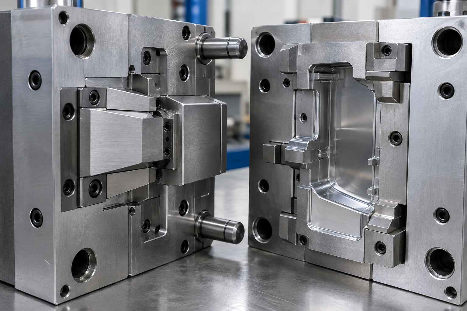
A good injection mold shut-off design does more than prevent flash during the first mold trial. It must also keep sealing well after thousands of molding cycles.
This is where many mold problems begin.
A shut-off may look fine during T1. The parts are clean, and there is no visible flash. However, after production starts, the same area may develop flash, scratches, steel wear, or galling.
In many cases, the problem is not only injection pressure or clamping force. The real cause may be poor shut-off geometry, weak contact, wrong steel, or inaccurate fitting.
For this reason, buyers should review the injection mold shut-off design before steel cutting. This is especially important around sliders, lifters, inserts, side holes, and complex parting surfaces.
What Is an Injection Mold Shut-Off?
A shut-off is an area where two mold steel surfaces close against each other. Its job is to stop molten plastic from flowing outside the cavity.
Common shut-off areas include:
- Slider-to-core interfaces
- Slider-to-cavity interfaces
- Lifters
- Core and cavity intersections
- Inserts
- Side holes
- Undercuts
- Complex parting surfaces
Unlike a simple flat parting line, many shut-offs work at an angle.
When the mold closes, one steel surface may slide slightly against another. Because of this, the shut-off must seal tightly without creating too much friction.
This is why injection mold shut-off design affects both flash and long-term mold wear.
For products with complex parting surfaces, our guide to parting line design rules explains how mold separation affects flash and tooling structure.
Why Poor Injection Mold Shut-Off Design Causes Flash
Flash means molten plastic has found a gap.
Sometimes that gap comes from the molding process. For example, injection pressure may be too high. Clamping force may also be too low.
However, if flash always appears in the same shut-off area, the mold should be checked.
Shut-Off Angle Is Too Small
A small shut-off angle creates more sliding contact.
As the mold closes, the steel surfaces may rub heavily. Over time, this can cause scratches, galling, and local wear.
Once the edge begins to wear, the clearance becomes larger. Flash can then appear.
Typical problems include:
- Scratches
- Galling
- Rounded edges
- Steel wear
- Increasing clearance
- Repeated flash
There is no single angle that works for every mold.
The correct angle depends on product geometry, slider direction, available space, steel condition, and required mold life.
Still, when the part design allows it, a steeper and more stable shut-off is usually safer than two nearly parallel steel surfaces.
A designer should not only ask:
“Can this structure be molded?”
A better question is:
“Can this shut-off remain stable during long-term production?”
Shut-Off Area Is Too Small
Another common problem is a narrow contact area.
If only a small steel surface resists injection pressure, the load becomes concentrated. As a result, that area wears faster.
At first, the mold may still produce acceptable parts. Later, even a small amount of wear can create a gap.
Operators may try to reduce injection pressure or increase clamping force. However, this only hides the real problem.
The flash often returns.
Our guide to injection mold flash explains the difference between process-related flash and tooling-related flash.
Injection Mold Shut-Off Design Needs Good Steel Contact
The angle alone does not determine whether an injection mold shut-off design is reliable.
Actual steel contact is just as important.
For example, a slider may appear to have a large shut-off surface in CAD. After machining and fitting, only part of that surface may touch the opposite steel.
Several issues can cause this:
- CNC machining deviation
- EDM deviation
- Slider positioning error
- Poor spotting
- Insert height differences
- Guide clearance
- Mold plate deformation
- Incorrect fitting
When contact is uneven, pressure becomes concentrated in one area.
The mold may still pass T1. However, after repeated opening and closing, the heavily loaded section can wear quickly.
Therefore, the mold maker should check the real contact pattern. CAD dimensions alone are not enough.
At Fentor Mold, shut-off surfaces are treated as functional fitting areas. They are not handled like ordinary machined surfaces.
Accurate machining is also important for inserts and moving components. You can learn more about our precision mold components manufacturing capabilities.
Avoid Excessive Preload in Injection Mold Shut-Off Design
Making a shut-off extremely tight may seem safer.
In practice, too much preload can create another problem.
If two steel surfaces press too hard against each other, they may seal well at first. However, the high contact force increases friction.
This is especially risky for moving shut-offs.
For example, a slider may contact the core before reaching its final position. If the interference is too large, every cycle creates extra rubbing.
Over time, this may cause:
- Bright wear marks
- Scratches
- Steel powder
- Galling
- Difficult slider movement
- Damaged shut-off edges
- Increasing flash
Good injection mold shut-off design needs controlled contact. It should not rely on the tightest possible fit.
The slider also needs proper guidance and locking support. The shut-off surface should not carry all molding pressure by itself.
If a slider becomes loose, shut-off wear can increase quickly.
Our injection mold slide jamming guide covers slider clearance, wear plates, alignment, and locking surfaces in more detail.
Steel Selection Affects Injection Mold Shut-Off Wear
Shut-off surfaces contact each other again and again.
Because of this, steel condition matters.
Important factors include:
- Steel grade
- Hardness
- Heat treatment
- Surface treatment
- Contact pressure
- Sliding distance
- Mold life
- Plastic material
For example, a mold running glass-filled plastic may need stronger wear resistance than a mold producing standard PP or ABS.
A short-run mold may also use a different solution from a mold designed for hundreds of thousands of cycles.
In some critical areas, replaceable inserts are useful.
Instead of machining the shut-off directly into a large core, the mold maker can use a smaller insert. If wear appears later, that insert can be repaired or replaced.
This can reduce maintenance cost and shorten repair time.
Slider Injection Mold Shut-Off Design Needs Extra Attention
Slider shut-offs are among the most sensitive areas in a mold.
They combine several risks:
- Horizontal movement
- Angular contact
- Locking force
- Machining tolerance
- Wear
- Thermal expansion
- Injection pressure
The slider must reach the same position every cycle.
More importantly, the locking structure behind the slider must support molding pressure.
If the slider relies mainly on the front shut-off surface, injection pressure may slowly push it backward.
Even a very small movement can create flash.
For a reliable injection mold shut-off design, engineers should check the full force path:
cavity pressure → slider → locking surface → mold plate
The shut-off edge should not carry the full load.
This is especially important for large sliders and long side shut-off lines.
Injection Mold Shut-Off Design Should Avoid Fragile Steel
Some product geometries create thin or sharp steel at the shut-off.
These areas may look acceptable in CAD. However, they can be weak in real production.
Thin shut-off steel may:
- Chip during assembly
- Deform under pressure
- Wear quickly
- Be damaged during polishing
- Become difficult to repair
Where possible, the product design should leave enough steel around the shut-off.
This is one reason DFM review is important before mold manufacturing begins.
A small product change before steel cutting may create a much stronger mold structure. After machining, the same change may require welding, EDM, CNC rework, and another mold trial.
Fentor Mold normally reviews these areas before tooling starts. Preventing a weak shut-off is much easier than repairing it later.
How to Check Injection Mold Shut-Off Design During T1
T1 is not only about checking whether the part has flash.
The mold team should also inspect the shut-off itself.
Useful checks include:
- Is there abnormal rubbing?
- Are contact marks even?
- Does one corner show heavier contact?
- Are there scratches?
- Is the slider moving smoothly?
- Does the slider return to the same position?
- Is flash concentrated in one area?
- Does flash increase with molding pressure?
- Is there steel powder?
- Are sharp edges starting to round?
These signs can reveal an injection mold shut-off design problem before serious damage develops.
Some problems are easy to hide during sample approval.
For example, reducing injection pressure may remove flash. However, the process window may then become too narrow.
Later, material changes or machine variation can bring the flash back.
A good mold should work within a reasonable process window. It should not depend on unusually low pressure to protect a weak shut-off.
Why Injection Mold Shut-Off Wear Appears Later
Not every mold problem appears during T1.
Shut-off wear is a common example.
During the first few hundred shots, the mold may look normal. After many production cycles, small fitting problems can become more serious.
Repeated contact can gradually increase problems such as:
- Poor alignment
- Excessive preload
- Weak locking
- Low hardness
- Small shut-off angles
- Narrow contact areas
- Loose sliders
Flash is often one of the first visible signs.
Therefore, buyers should not judge a mold only by the first samples.
Our guide to injection mold wear inspection explains what to check when an older mold becomes less stable.
What Buyers Should Check Before Approving the Design
Buyers do not need to review every mold dimension.
However, for parts with complex shut-offs, several areas deserve attention during DFM or mold design review.
Check:
- Shut-off location
- Shut-off direction
- Shut-off angle
- Steel thickness
- Slider locking method
- Replaceable inserts
- Steel grade
- Steel hardness
- Long sliding contact areas
- Thin or fragile steel
- Future repair access
For critical areas, ask the mold supplier to show a section view.
A section view makes the shut-off angle, steel thickness, slider position, and locking method easier to understand.
It is often more useful than looking only at the full 3D mold assembly.
Final Thoughts on Injection Mold Shut-Off Design
A good injection mold shut-off design should not be judged only by T1 samples.
The real question is whether the shut-off can still close accurately after long-term production.
Reliable designs usually have enough shut-off angle, strong steel, stable support, accurate machining, and proper fitting.
For sliders and other moving components, the locking system is especially important. The shut-off seals the cavity, while the structure behind it carries the load.
If your part contains side holes, clips, sliders, lifters, or intersecting surfaces, review the shut-off areas before mold manufacturing begins.
A small design improvement at this stage can prevent repeated flash repair, welding, polishing, and downtime later.
For custom tooling projects, you can learn more about our injection mold manufacturing service or send your 3D files to Fentor Mold for a DFM review.