
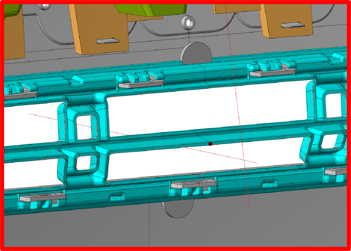
The right injection mold gate location can strongly affect filling pressure, weld lines, air traps, warpage, part appearance, and production stability.
A gate can have the correct size but still cause problems if it is placed in the wrong position.
For example, moving a gate only a few millimeters can change the entire flow path. One location may create balanced filling, while another may cause weld lines, trapped air, uneven packing, or warpage.
Therefore, gate placement should be reviewed during DFM and mold design, not after the mold has already been machined.
For custom tooling projects, Fentor Mold provides injection mold manufacturing from DFM and mold design through tooling, trial, and delivery.
What Is Injection Mold Gate Location?
The injection mold gate location is the point where molten plastic enters the mold cavity from the runner system.
A simple flow path is:
Injection Unit → Sprue → Runner → Gate → Mold Cavity
The gate position determines where the plastic flow begins.
As a result, it affects:
- Flow length
- Filling time
- Injection pressure
- Weld-line position
- Air traps
- Packing pressure
- Shrinkage
- Warpage
- Surface appearance
A good gate location makes these factors easier to control.
Why Injection Mold Gate Location Matters
A poor gate location can create defects that are difficult to fix by changing molding parameters alone.
For example, if the gate is placed too far from a thin section, the melt may lose pressure and temperature before reaching that area.
This can increase the risk of:
- Short shots
- High injection pressure
- Flow hesitation
- Uneven filling
- Weld lines
- Surface defects
However, simply moving the gate closer is not always the answer.
The flow direction, weld-line position, appearance, and mold structure must also be considered.
How Injection Mold Gate Location Affects Flow Length
Flow length is one of the first factors to review.
Long flow paths increase pressure loss.
They can also reduce melt temperature before the material reaches the end of the cavity.
This is especially important for:
- Thin-wall parts
- Large housings
- Long covers
- Automotive parts
- High-viscosity materials
Therefore, the injection mold gate location should provide a reasonable flow distance.
If one area is too far from the gate, another gate location or multiple gates may be required.
How Injection Mold Gate Location Affects Pressure
Plastic must overcome resistance as it flows through the cavity.
The farther it travels through narrow sections, the higher the pressure loss can become.
This problem becomes more serious with:
- Thin walls
- Long flow lengths
- High-viscosity materials
- Small gates
- Low melt temperature
A better gate location can reduce unnecessary pressure loss.
As a result, the molding process may have a wider and more stable processing window.
Injection Mold Gate Location and Wall Thickness
Wall thickness should be reviewed early.
Plastic normally flows more easily through thicker areas than very thin sections.
Therefore, engineers often try to place the gate so the material flows from a more favorable area toward thinner sections.
However, the gate should not simply be placed on the thickest wall.
The final decision should also consider:
- Part geometry
- Flow length
- Appearance
- Ejection
- Weld lines
- Cooling
- Material behavior
For parts with large thickness changes, poor gate location can also create uneven packing.
Injection Mold Gate Location and Weld Lines
Weld lines form when two or more plastic flow fronts meet.
Their location is strongly affected by gate placement.
For example, plastic may split around a hole, boss, or core and then meet again.
If that meeting point is on a visible or structural area, the weld line may become a problem.
Therefore, the gate should be positioned so that unavoidable weld lines appear in less critical areas.
For cosmetic products, this is especially important.
Injection Mold Gate Location and Air Traps
Gate position also affects how air moves inside the cavity.
As plastic fills the mold, air must escape.
If the flow surrounds an area too quickly, trapped air may create:
- Burn marks
- Short shots
- Poor surface quality
- Gas-related defects
- Local pressure problems
Therefore, gate location and venting should be reviewed together.
Sometimes moving the gate can direct trapped air toward the parting line or another venting area.
However, poor venting cannot always be fixed by gate location alone.
Protect Cosmetic Surfaces
The gate always leaves some type of gate mark.
For internal parts, this may not matter.
However, for cosmetic parts, gate marks may need to be hidden.
Before selecting the injection mold gate location, ask:
- Which surfaces are visible?
- Which surfaces are hidden after assembly?
- Where can the gate mark be placed?
- Is automatic trimming required?
- Does the customer have appearance standards?
For example, the back of a housing is usually a better gate location than the front decorative surface.
This is especially important for:
- High-gloss parts
- Transparent parts
- Painted parts
- Textured housings
- Consumer products
Injection Mold Gate Location and Parting Line
The best theoretical gate location still has to work with the mold structure.
Gate placement can affect:
- Mold opening
- Runner layout
- Ejection
- Slider movement
- Core and cavity design
- Parting line
- Machining access
Therefore, gate location should never be selected separately from the overall mold design.
The gate, runner, cavity, ejection, cooling, and parting line must work as one system.
Single Gate vs Multiple Gates
A single gate is often enough for simple parts.
Advantages include:
- Simpler runner design
- Lower tooling complexity
- Easier maintenance
- Fewer weld lines
However, a single gate may create excessive flow length on large parts.
Multiple gates can shorten the flow distance.
They can also reduce filling pressure.
However, more gates introduce new issues:
- More weld lines
- Flow-front interaction
- Packing differences
- More complex hot runner control
Therefore, more gates are not automatically better.
The goal is balanced and controlled filling.
Injection Mold Gate Location in Multi-Cavity Molds
Gate location is even more important in multi-cavity molds.
Each cavity should receive plastic under similar pressure and temperature conditions.
If runner resistance or gate position is different, some cavities may fill earlier than others.
This can lead to:
- Different part weights
- Dimensional variation
- Different packing levels
- Surface differences
- Cavity-to-cavity warpage
Therefore, gate location and runner balance should be reviewed together.
For more detail, see our Injection Mold Filling Balance guide.
How Material Affects Injection Mold Gate Location
Different plastics behave differently during filling.
Important material factors include:
- Viscosity
- Melt temperature
- Mold temperature
- Shrinkage
- Fiber content
- Surface requirements
- Wall thickness
For example, glass-filled materials can show different flow and shrinkage behavior from unfilled plastics.
High-viscosity materials may also need shorter flow paths or larger gates.
Therefore, gate location should be based on the actual production material, not only the general material family.
Injection Mold Gate Location and Warpage
Gate placement can influence warpage because it affects filling and packing.
If one section receives more packing pressure than another, shrinkage may become uneven.
The risk is higher for:
- Large flat parts
- Thin-wall housings
- Long rectangular parts
- Uneven wall thickness
- Glass-filled plastics
A better gate location can improve packing balance.
However, warpage is not caused by gate location alone.
Cooling, material shrinkage, wall thickness, mold temperature, and process settings also matter.
Should You Use Moldflow for Gate Location?
For simple parts, experienced engineers can often choose a suitable gate location based on geometry and material.
For complex parts, Moldflow analysis can provide useful information before steel is cut.
Simulation can compare:
- Filling time
- Injection pressure
- Flow-front temperature
- Weld-line location
- Air traps
- Clamp force
- Packing
- Warpage
For example:
Position A: Low pressure, but poor weld-line location
Position B: Good appearance, but high filling pressure
Position C: Slightly higher pressure, but better overall quality
In this case, Position C may be the best engineering choice.
The goal is not simply to find the lowest pressure.
Instead, the best injection mold gate location balances filling, appearance, quality, and tooling requirements.
Common Injection Mold Gate Location Mistakes
Choosing the Easiest Machining Position
The easiest gate to machine is not always the best gate for the plastic part.
Molding performance should come first.
Ignoring Appearance
A technically good gate may still leave an unacceptable mark.
Therefore, appearance requirements should be confirmed before mold design is released.
Making the Flow Path Too Long
Excessive flow length can increase pressure and filling problems.
Ignoring Weld Lines
Poor gate placement can move weld lines into visible or structural areas.
Using Too Many Gates
Multiple gates can reduce flow length.
However, they also create more weld lines and flow interaction.
Choosing the Gate Too Late
Changing gate location after steel machining can be expensive.
Therefore, gate placement should be confirmed during DFM.
Gate Location vs Gate Size
Gate location and gate size are related, but they solve different problems.
Gate location controls where the melt enters and how it flows through the part.
Gate size controls restriction, pressure loss, shear, packing, and gate freeze.
Therefore, changing gate size cannot always solve a bad gate location.
For more detail, see our Injection Mold Gate Size Calculation guide.
In practice, engineers should evaluate:
Gate Location + Gate Type + Gate Size + Runner Design
as one system.
Injection Mold Gate Location Checklist
Before approving the mold design, check:
| Check Item | What to Review |
|---|---|
| Flow path | Is the flow distance reasonable? |
| Wall thickness | Does the gate support stable filling? |
| Weld lines | Are they in acceptable areas? |
| Air traps | Can trapped air escape? |
| Appearance | Is the gate mark acceptable? |
| Material | Is the gate suitable for the resin? |
| Parting line | Does the location work with mold structure? |
| Ejection | Will the gate interfere with ejection? |
| Runner balance | Is filling balanced? |
| Multiple gates | Are they really necessary? |
| Warpage | Has packing balance been reviewed? |
| Moldflow | Is simulation needed? |
A short review at the design stage can prevent expensive mold changes later.
What Buyers Should Ask the Mold Supplier
Before approving the mold design, buyers should ask:
- Where is the proposed gate location?
- Why was this position selected?
- Where will weld lines appear?
- Where will the gate mark be visible?
- Is the flow length acceptable?
- Is one gate enough?
- Is Moldflow needed?
- Does the gate affect ejection or parting line?
- Is the gate suitable for the selected material?
- Can the gate be modified easily after T1?
These questions are especially useful for custom molds.
They also help buyers understand whether the supplier has reviewed the complete production process rather than only the first trial.
If the mold will remain with the supplier for production, Fentor Mold can also validate gate performance through its injection molding production service.
Final Takeaway
The best injection mold gate location is not simply the position that fills the cavity fastest.
A good gate location should balance:
- Flow length
- Pressure
- Weld lines
- Air traps
- Packing
- Warpage
- Appearance
- Mold structure
For simple parts, the decision may be straightforward.
However, large, thin-wall, cosmetic, multi-cavity, or complex parts need more careful review.
Therefore, gate location should be confirmed before mold manufacturing begins.
Good gate placement can reduce mold modifications, improve part quality, and make production more stable.