
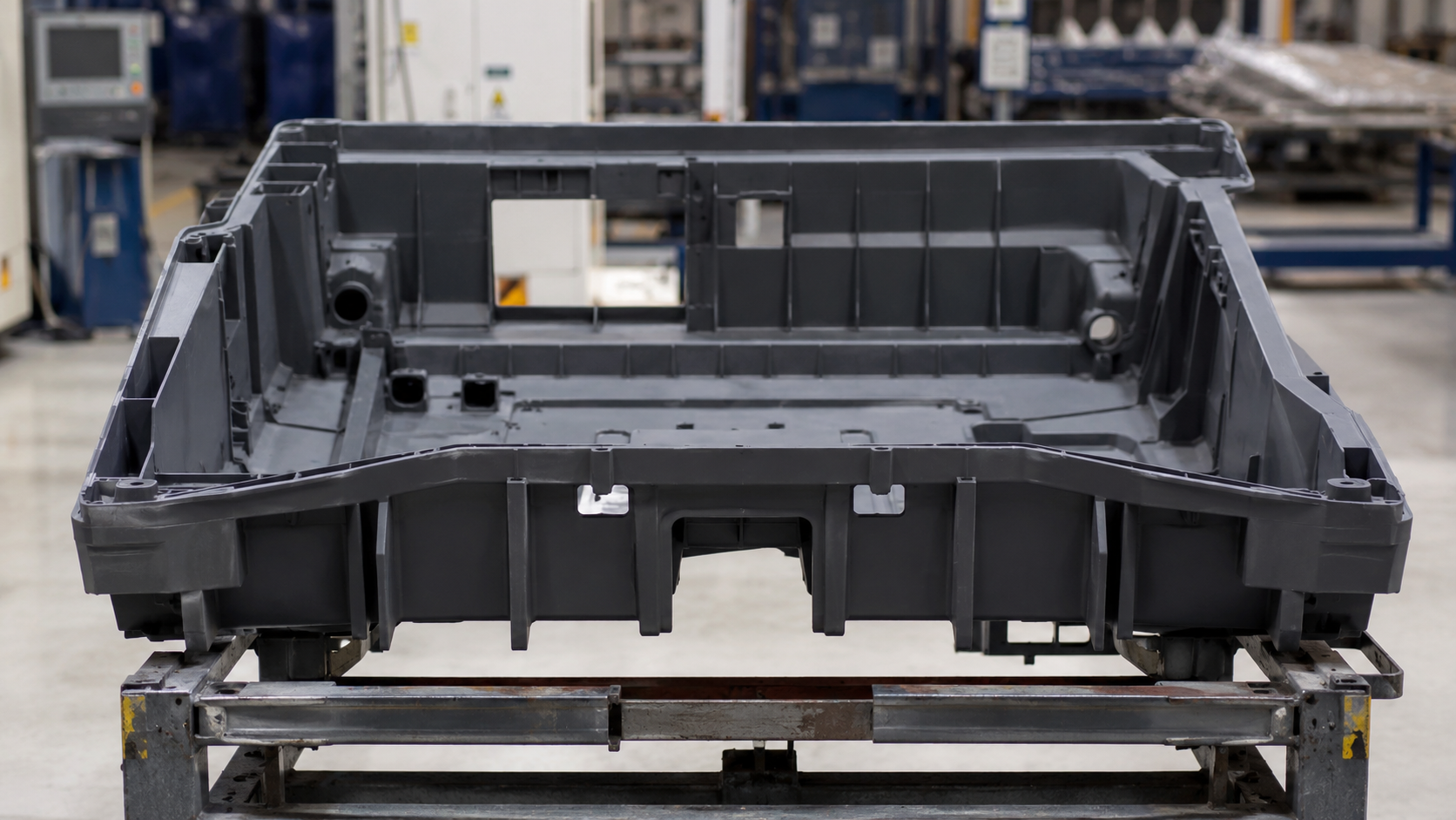
Injection molding large parts requires much more control over machine size, filling, cooling, mold design, and process stability than molding smaller plastic components. As the part becomes larger, the flow length increases, the projected area grows, and differences in wall thickness or cooling can have a much greater effect on the final part.
Machine selection also becomes more complicated. A machine may have enough clamping force but not enough shot capacity, or the mold may simply be too large for the tie-bar spacing. For buyers, successful large-part molding depends on matching the part design, mold, material, machine, and process from the beginning.
This guide explains the main engineering issues behind injection molding large parts, including machine selection, filling, warpage control, mold design, material choice, and supplier evaluation.
What Is Injection Molding Large Parts?
There is no fixed dimension that officially defines a large injection molded part.
A 500 mm part may be considered large for one factory but routine for another. The real question is how demanding the part is relative to the mold and machine required to produce it.
Typical large molded products include:
- Automotive interior and exterior panels
- Appliance housings and panels
- Industrial equipment covers
- Large electrical enclosures
- Storage and structural components
- Machine guards
- Large plastic frames
- Furniture and consumer-product housings
For injection molding large parts, overall dimensions are only one consideration. Part weight, projected area, wall thickness, flow length, material, surface requirements, and dimensional tolerances can be just as important.
A relatively thin but wide panel, for example, may be more difficult to fill than a smaller and heavier part.
Why Injection Molding Large Parts Is More Difficult
The main difficulty is scale.
With a small part, the melt may travel only a short distance before the cavity is filled. With a large part, plastic may need to travel several hundred millimeters from the gate while maintaining enough temperature and pressure to reach the end of the cavity.
This can increase the risk of:
- Short shots
- Flow marks
- Weld lines
- Air traps
- Uneven packing
- Sink marks
- Warpage
- Dimensional variation
The mold itself is also heavier and more demanding.
Large molds require enough steel thickness to resist deformation during injection. Cooling channels must cover a much greater area. Slides, lifters, ejectors, hot-runner systems, and support structures may also become larger and more complicated.
This is why injection molding large parts should be evaluated as a complete tooling and production system rather than only as a machine-capacity question.
Machine Requirements for Injection Molding Large Parts
One of the first questions buyers often ask is:
What size injection molding machine do I need?
Machine tonnage matters, but tonnage alone does not give the answer.
Several machine specifications should be checked together.
Clamping Force
During injection, plastic pressure creates force that tries to open the mold.
The required clamping force depends mainly on:
- Part projected area
- Runner projected area
- Cavity pressure
- Number of cavities
- Plastic material
Large parts generally have a large projected area, so clamping-force requirements can increase quickly.
However, simply choosing the highest-tonnage machine available is not always the best solution. An unnecessarily large machine can increase production cost without solving problems caused by poor part or mold design.
Shot Size
The machine must have enough injection capacity to fill:
- The molded part
- Runner system
- Sprue
- Hot-runner volume where applicable
Shot weight should not be evaluated only by comparing part weight with the machine’s theoretical maximum shot weight.
The screw should operate within a suitable working range so that melt preparation remains stable and repeatable.
This becomes particularly important when injection molding large parts made from engineering plastics or materials with narrow processing windows.
Tie-Bar Spacing and Platen Size
Sometimes the problem is not tonnage at all.
A mold may require a 500-ton machine based on projected area but still fail to fit a particular 500-ton machine because the mold is too wide to pass between the tie bars.
Check:
- Mold length
- Mold width
- Mold height
- Tie-bar spacing
- Platen dimensions
- Mold weight
- Maximum opening stroke
- Ejector stroke
Our article on Injection Mold Size: How to Measure and Specify It explains these machine-to-mold compatibility checks in more detail.
Machine suitability should ideally be confirmed before the mold base is finalized, not after machining has already started.
Filling Challenges in Injection Molding Large Parts
Getting plastic into a large cavity is not simply a matter of increasing injection pressure.
If the flow path is too long, the melt can cool before reaching the end of the cavity. Increasing pressure may temporarily improve filling, but it can create other problems such as flash, excessive molded-in stress, or uneven packing.
A better approach is to review the complete filling system.
Gate Position
Gate location has a major influence on:
- Flow distance
- Weld-line position
- Pressure loss
- Packing
- Orientation
- Warpage
For a large panel, placing one small gate at one end may create an unnecessarily long flow path.
Depending on the geometry, engineers may consider:
- Multiple gates
- Fan gates
- Edge gates
- Valve gates
- Sequential valve gating
- Hot-runner systems
The correct choice depends on the part rather than a fixed rule.
Runner Size and Flow Balance
The runner must deliver enough material without excessive pressure loss.
When multiple gates or cavities are used, flow balance becomes particularly important. One area filling early while another is still struggling to fill can produce very different pressure and shrinkage conditions across the part.
For a deeper explanation of runner resistance, gate restriction, and pressure distribution, see our article on Injection Mold Filling Balance and Runner & Gate Design.
For difficult projects, mold-flow analysis before steel cutting can identify potential filling problems much earlier.
Wall Thickness Design for Large Plastic Parts
Making a large plastic part thicker does not automatically make it easier to mold.
Excessive thickness can lead to:
- Longer cooling time
- Sink marks
- Internal voids
- Greater shrinkage
- Higher material consumption
- Increased cycle cost
At the same time, a wall that is too thin can make the cavity difficult to fill.
The objective is usually to keep the wall thickness reasonably uniform while using ribs, gussets, curves, or structural features where additional stiffness is required.
Sudden transitions from thin to thick sections should be reviewed carefully.
On large panels, even a relatively small change in wall thickness can change how the material flows and cools across a large distance.
Good injection molding large parts design is therefore not about adding more plastic. It is about placing material where it actually improves performance.
Cooling Control in Injection Molding Large Parts
A large part can look acceptable when the mold opens and still deform later.
This often happens because different areas of the part cool and shrink at different rates.
Imagine one side of a large housing sitting close to efficient cooling channels while another area contains thicker ribs and receives less cooling. The two areas will not shrink in the same way.
The result may be:
- Bowing
- Twisting
- Edge lift
- Local distortion
- Dimensional drift
For large molds, cooling-channel layout should be reviewed together with cavity geometry.
Engineers may need to consider:
- Channel distance from the molding surface
- Channel spacing
- Separate cooling circuits
- Core cooling
- Baffles
- Bubblers
- Inserts with improved thermal conductivity
- Independent temperature control
Increasing cooling time can sometimes reduce deformation, but it is not a good substitute for poor cooling design.
Longer cycles directly increase part cost.
How to Control Warpage in Injection Molding Large Parts
Warpage is one of the most common concerns when injection molding large parts, particularly for wide panels, housings, covers, and thin-wall products.
Possible causes include:
- Uneven wall thickness
- Poor gate location
- Uneven packing pressure
- Unbalanced cooling
- Material shrinkage
- Fiber orientation
- Insufficient structural stiffness
- Poor part geometry
Trying to correct all of these problems through molding parameters after the mold is finished can become expensive.
For example, increasing holding pressure may improve one area but create excessive stress somewhere else. Extending cooling time may reduce deformation but make the production cycle commercially unattractive.
It is usually better to review the part geometry, material, gate plan, cooling layout, and expected shrinkage during DFM and mold design.
Mold Strength for Large Injection Molded Parts
A large cavity needs a mold structure capable of resisting repeated injection and clamping loads.
Insufficient support can lead to:
- Mold plate deflection
- Flash
- Parting-line problems
- Dimensional variation
- Premature mold wear
Large molds often require stronger support structures, properly sized mold plates, support pillars, suitable steel, and careful cavity positioning.
The mold should also be designed around the machine that will actually run it.
If you are developing tooling for a large plastic component, our custom injection mold manufacturing service covers DFM, mold-flow evaluation, mold design, tooling, trial, and production preparation.
The important point is to resolve machine and mold requirements together rather than designing the tooling first and searching for a machine afterward.
Ejection Design for Large Plastic Parts
Large parts usually have a large contact area with the mold.
As the plastic cools, it can shrink tightly around cores and textured surfaces. If the ejection force is concentrated in only a few locations, the part may deform or show visible ejector marks.
Possible ejection methods include:
- Ejector pins
- Ejector sleeves
- Stripper plates
- Air assistance
- Hydraulic ejection
- Combination systems
Large flat parts normally benefit from distributing the ejection force across multiple suitable locations.
Draft angle also matters.
Insufficient draft may not be obvious from a CAD model, but it can create serious release problems once a large surface is molded.
Material Selection for Large Part Injection Molding
Different plastics behave very differently in a large cavity.
PP, ABS, PC, PA, PC/ABS, and glass-filled materials have different:
- Flow characteristics
- Shrinkage rates
- Melt temperatures
- Mold-temperature requirements
- Moisture sensitivity
- Mechanical properties
A material selected only from a mechanical-property datasheet may create unexpected molding problems.
For example, a high glass-fiber content may improve stiffness but can increase directional shrinkage and warpage. A resin with poor flow may require a different wall thickness or gate strategy.
Material selection should therefore consider both product performance and moldability.
Surface Quality of Large Injection Molded Parts
Large visible surfaces can expose defects that would hardly be noticed on a small component.
These may include:
- Flow lines
- Gloss differences
- Weld lines
- Gate blush
- Sink marks
- Texture variation
- Stress whitening
For an internal industrial cover, minor appearance variation may be acceptable.
For an automotive interior panel or appliance front panel, it may not be.
The supplier should understand the cosmetic requirement before mold design begins because gate location, texture, venting, cooling, and filling strategy may all depend on it.
How to Choose a Supplier for Injection Molding Large Parts
Supplier selection should go beyond asking for the maximum machine tonnage.
A useful RFQ discussion should cover the following points.
Can the Supplier Review the Part Before Quoting the Mold?
A supplier should be able to identify obvious risks such as:
- Long flow paths
- Problematic wall-thickness changes
- Poor draft
- Difficult undercuts
- Likely warpage areas
- Gate-location limitations
If the only response is a mold price based on the 3D file, important engineering questions may have been missed.
Is the Intended Production Machine Known?
Ask which machine will be used for sampling and production.
Confirm:
- Machine tonnage
- Shot capacity
- Tie-bar spacing
- Platen size
- Maximum mold dimensions
These details are more useful than a general statement such as “we have large machines.”
Can Tooling and Production Be Evaluated Together?
The best results usually come when mold design decisions are made with the actual production process in mind.
Our Injection Molding Production service covers mold trials, process optimization, material handling, dimensional inspection, and production support.
For injection molding large parts, this connection between tooling and production is especially important because filling, cooling, machine selection, and part deformation are closely linked.
What Happens During Mold Trials?
One good T1 sample does not prove that the process is stable.
During trials, the supplier should evaluate more than appearance.
Depending on the project, this may include:
- Part weight
- Key dimensions
- Filling behavior
- Warpage
- Cycle time
- Mold temperature
- Injection pressure
- Holding pressure
- Ejection
- Repeatability
Buyers should ask what will be measured and what trial information will be provided.
RFQ Information for Injection Molding Large Parts
For injection molding large parts, a clear RFQ can save a surprising amount of time.
Try to provide:
- 3D CAD file
- 2D drawing if available
- Plastic material and grade
- Surface finish or texture requirement
- Color
- Expected annual volume
- Critical dimensions
- Assembly requirements
- Cosmetic requirements
- Preferred production location
- Target injection machine if already defined
If the material has not been finalized, explain the required performance instead of choosing a resin only to complete the RFQ.
For example:
“Outdoor housing, UV resistant, impact resistant, operating temperature -20°C to 80°C.”
That gives the engineering team more useful information than simply writing “plastic.”
Final Thoughts
Successful injection molding large parts starts long before the first molding trial.
Machine size must match both the mold and the required shot. The gate and runner system must fill the cavity without creating excessive pressure loss. Cooling needs to control shrinkage across a large area, and the mold structure must remain stable under repeated production loads.
Part design is equally important.
Uniform walls, sensible rib design, suitable draft, realistic tolerances, and an appropriate resin can eliminate many problems before the mold is built.
When comparing suppliers, do not focus only on machine tonnage or tooling price. Ask how the supplier plans to fill the part, control warpage, cool the mold, select the production machine, eject the component, and verify quality during trials.
Those answers usually tell you much more about whether the supplier can handle the project successfully.